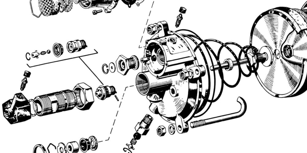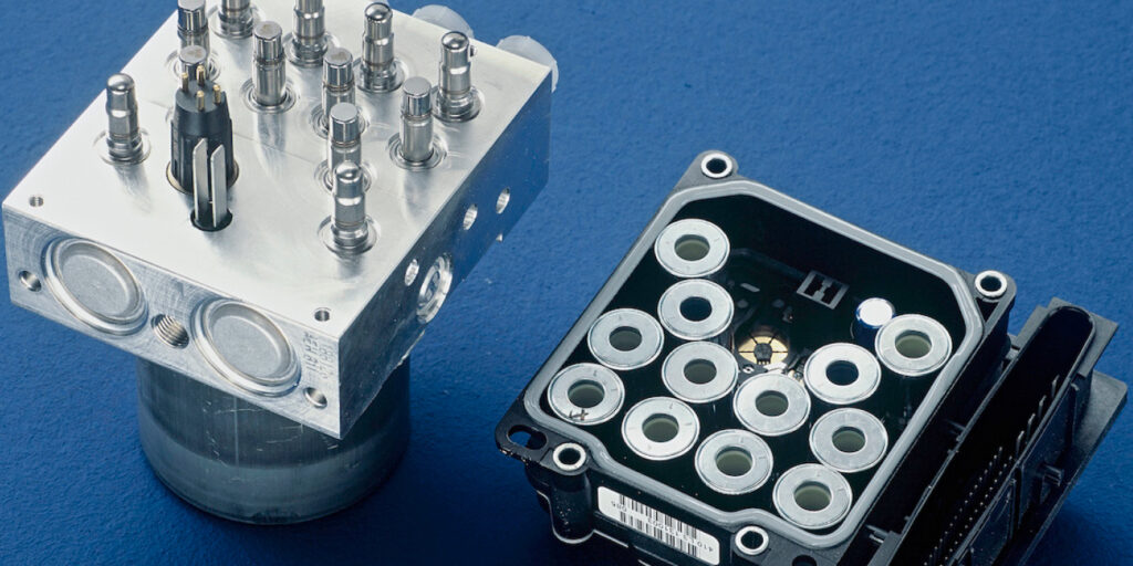
The ABS controller/modulator is the heart of any ABS or ESC system. The modulator gets the brake pressure from the master cylinder. Inside are the valves and solenoids that control the pressures to the wheel. During normal operation, the pressure from the master cylinder goes through the HCU unaltered. The exception to this rule is vehicles with electronic brake distribution.
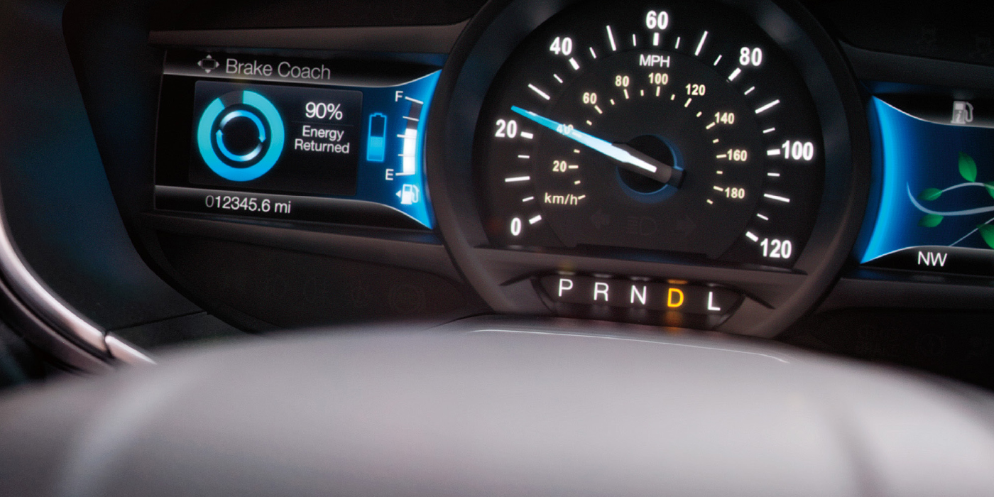
ABS is the foundation of the ESC system. ESC systems add software and sensors like yaw, steering angle and even control of the throttle to keep the vehicle under control.
BASICS
A basic ABS four-channel system will have eight solenoids (four isolation/four dump), or two for each wheel. Some systems will have more solenoids or valves to isolate the master cylinder from the HCU. ESC systems will typically have 12 or more.
When the master cylinder applies pressure, it goes directly to the wheel because the outlet/dump solenoid is closed. This is a normal braking event. The unit is in a “passive” state.
If the system senses a wheel is locked, the inlet/isolation solenoid is closed to prevent any more pressure from the master from reaching the wheel. The wheel might start to turn.
If the wheel does not start to turn, the outlet/dump valve will open. This will release or bleed off the hydraulic pressure that is holding the wheel. The wheel will now rotate.
Since pressure from the master cylinder has been bled off, the pump in the HCU will spool up and apply pressure. The outlet valve is closed and the inlet valve is opened. The pump applies pressure to the wheel. If the wheel is still outside the wheel slip parameters, the cycle will start over.
HCU MECHANICAL PROBLEMS
Mechanical issues with the HCU are rare, but they can happen. Valve seats and pintles can become stuck or not seat properly due to debris, corrosion or contaminated brake fluid.
If the inlet/isolation valve is stuck open, it will not affect normal braking in any way. It will only hurt the ABS system. This could lead to a pulling condition during ABS activation.
If an outlet/dump valve is stuck open in one circuit, this could cause a pull condition during normal braking. This is due to the loss of brake pressure at a wheel.
Testing Solenoids Electrically
Sometimes a stuck or defective solenoid or pump will set a code. A solenoid has a resistance between 2 and 8 ohms. On some units, it is impossible to access the individual solenoids. Testing the unit with a scan tool with bidirectional control might be the best way to confirm the condition of the HCU.
Most vehicles equipped with ESC will have 12 valves or solenoids in the HCU. Eight solenoids control the wheels. Four additional solenoids can block off the master cylinder and allow the pump to send pressure to a specific wheel.
Understeer is a condition where the wheels are turned, but the vehicle continues to travel in a straight line. This is sometimes described as a push. The ESC computer would see this event through the sensors. The wheel speed sensors in the front typically read slower than in the rear. The computer would also see that the steering angle is greater than the intended path.
The ESC system needs to intervene before the event occurs, and it needs to anticipate the problem and correct as the vehicle travels. This is what the ESC sees during an understeer event. The SAS angle is at +52º, this means that the customer has the wheel turned to the right at a significant angle. Even with the steering wheel turned, the yaw and accelerometer read like the vehicle is going straight. The APPS, or throttle pedal position sensor, shows the driver is off the gas and the brake pedal is not pressed.
The deciding information for the system is in the wheel speed sensor inputs. Between the front and rear there is a 6 to 9 mph difference between the front and rear speeds. The front wheels are traveling slower than the rears.