When you receive a complaint that a brake pedal is too hard or soft, the diagnostic strategy must include everything from the rubber pedal cover to the type of friction material in the calipers. In between, you have a mixture of mechanical and hydraulic components that magnify the leg muscles of the driver. One of the most misdiagnosed components is the vacuum brake booster.
Vacuum brake boosters will probably be with us for a long time. It is the most efficient and economical way to amplify the force exerted by the driver. But where the booster gets its vacuum is changing. Many import and domestic nameplates use vacuum pumps to power the brake booster on their gas, diesel and even electric-powered vehicles.
For a vacuum brake booster to work, it needs a vacuum source. In the past, all that was required was a port on the intake manifold. Now, vacuum pumps are the choice for negative pressure power.
Why a Vacuum Pump?
In every piston engine, vacuum is generated during the intake stroke as the piston goes down in the cylinder and the intake valves are open. But modern engines have changed. Increased efficiency has reduced the amount of vacuum available to the brake booster. Engines have been downsized to 2.0 and even 1.4 liters. This means that there is less displacement to generate the vacuum.
Variable valve timing has further diminished the vacuum generated because the opening might be timed to allow a scavenging effect, so some intake air passes the exhaust valve. This air is intended for the catalyst so unburned hydrocarbons can be burned.
Turbocharging has also eliminated traditional vacuum in the intake manifold. The turbocharger produces positive pressure or boost in the intake manifold. The only time an engine might be under vacuum is when the engine is decelerating, and the throttle is closed.
What Type of Pump?
Vacuum pumps, typically diaphragm pumps, have been used on diesel engines for more than 40 years. These pumps were neither efficient nor reliable.
Most modern VWs use either an electric vacuum pump or a pump driven by a sprocket connected to the timing chain. These pumps use vanes attached to an offset shaft. As the shaft rotates, the vanes create a sealed chamber with the walls of the housing.
Since the shaft is offset, the chambers change in volume and produce a vacuum on the outlet side when turned. Electric pumps typically have multiple vanes; timing chain-powered pumps use just one vane.
Electric-powered vacuum pumps are controlled by the engine control module. The system uses a pressure sensor mounted between the pump and the booster. The ECM will look at the vacuum, brake pedal position and other engine parameters. The vacuum pump is controlled with a relay that is actuated by the engine control module. The pump is turned on for 2 to 3 seconds during startup.
Timing chain-powered pumps are lubricated with engine oil. The oil inlet is next to the shaft and is fed from the oil slung off the timing chain and sucked into the pump through a valve that controls the level of oil.
While it is rare for the vanes to wear out, it is possible for carbon and debris to enter the pump and cause damage to the vanes and housing. If the vanes can’t seal against the housing, a vacuum can’t be generated. The most common symptom of a worn pump is a hard brake pedal.
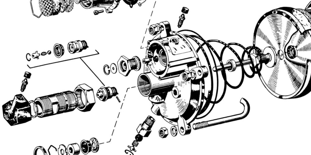
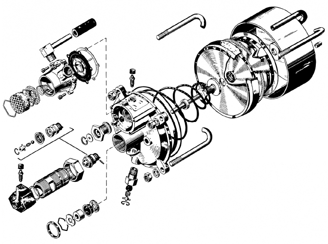
The Booster
No matter if the booster gets vacuum from the engine or a pump, if it is damaged, the brake pedal performance will change. The condition of the diaphragm inside the booster is also important. If it’s cracked, ruptured or leaking, it won’t hold vacuum and can’t provide much power assist. Leaks in the master cylinder can allow brake fluid to be siphoned into the booster, accelerating the demise of the diaphragm.
If there’s brake fluid inside the vacuum hose, it’s a good indication that the master cylinder is leaking and needs to be rebuilt or replaced. Wetness around the back of the master cylinder would be another clue for this kind of problem.
To check the vacuum booster, pump the brake pedal with the engine off until you’ve bled off all the vacuum from the unit. Then hold the pedal down and start the engine. You should feel the pedal depress slightly as the engine vacuum enters the booster and pulls on the diaphragm. No change? Then check the vacuum hose connection and engine vacuum. If it’s OK, the problem is in the booster, which needs to be replaced.
Brake Booster Math
A booster increases the force of the pedal, so a lower mechanical pedal ratio can be used. A lower ratio can give shortened pedal travel and better modulation. Most vacuum-boosted vehicles will have a 3.2:1 to 4:1 mechanical pedal ratio.
The size of the booster’s diaphragm and the amount of vacuum generated by the engine will determine how much force can be generated. Most engines will generate around -8 psi of vacuum (do not confuse with inches of HG or mercury). If a hypothetical booster with a 7-inch diaphragm is subjected to -8 psi of engine vacuum, it will produce more than 300 lbs. of additional force. Here is the math:
π(3.14) X radius(3.5)2 = 38.46 sq/inches of diaphragm surface area X 8 psi (negative pressure becomes positive force) = 307.72 lbs. of output force
To keep things simple, let’s return to our manual brake example. The rod coming from the firewall has 434 lbs. of output force. When the force is applied to the back of the master cylinder, the force is transferred into the brake fluid.
The formula for pressure is force divided by the surface area.
If the master cylinder has a 1-inch bore, the piston’s surface area is .78 square inches. If you divide the output force of 434 lbs. by the surface area of the piston, you would get 556 psi (434 lbs. divided by .78 inches) at the ports of the master cylinder. Not bad for 70 lbs. of human effort. If you reduce the surface area of the piston, you will get more pressure.
This is because the surface area is smaller, but the output force from the pedal stays the same. If you used a master cylinder with a bore of .75 inches that has a piston that has .44 inches of piston surface area, you would get 986 psi at the ports for the master cylinder (434 lbs. divided by .44 inches).
How that pressure is used at the calipers is another equation. The area of the caliper’s piston is also a circle with a surface that the 986 psi acts on. But there is also a consideration for the volume of fluid that is moved between the two components.
Brake pedal feel is directly connected to the sizing of the brake system components. On the mechanical side, you have the brake pedal pivot point and brake booster size. On the hydraulic side, you have the master cylinder and calipers. However, there are other variables like the friction materials, rotor diameter, and even the wheel and tire package.