When you use your scan tool to look at live data from an ADAS or other module, have you ever asked yourself how “live” the data really is and the path it took to be displayed as a value on your scan tool’s screen? The data you are looking at might be processed by one module, shared by another module and go through a gateway module to talk to your scan tool. How does it do it? Serial data buses.
Vehicle “data bus” units help to solve this dilemma by eliminating additional wiring and the need for multiple sensors. In the auto repair world, the term used to describe the design, layout and behavior of a serial data bus configuration is “topology.” So, why do you need to know about fancy topology? Simple: it influences how you access the modules with your scan tool. Also, it will change the way you look at the data retrieved by the scan tool.
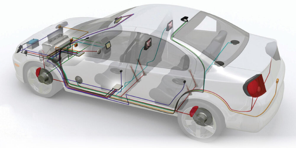
Modern vehicles typically have more than one serial data network and even more modules than before, which all must obey and conform to the topology the engineers have specified. And two-wire buses have a topology that dictates they are wired electrically in parallel.
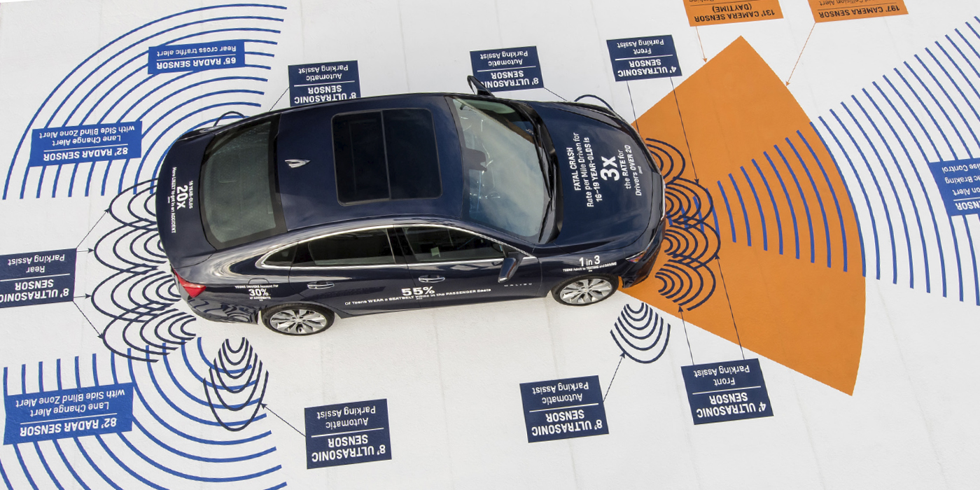
A module on a serial data bus is called a “node.” A scan tool also becomes a node on that bus. And even some sensors and switches can be nodes. The ADAS module will typically be connected to a high-speed data bus like CAN with modules for steering, ABS and the engine control module. Some vehicles might have a separate network for the ADAS modules. This is the case with the ASE L4 composite vehicle. To connect the two networks, the vehicle may use a gateway module. The gateway module might be a dedicated module, or, in some cases, it might be a module like the instrument cluster or engine control module that will act as a gateway by sharing vital information from the two networks.
On most automotive serial data buses, the peak voltage level might be 7 volts. This extra voltage is to accommodate resistance in the wires and ground problems that may cause voltage drops. The extra two volts gives the network a safety buffer that may help the vehicle as it ages.
If a signal was on an equal length of time as it was off, you would have 0, 1, 0, 1, 0, 1 as the binary message being sent out. It could represent what the throttle position voltage is, a signal being sent from the airbag module to the BCM reporting the status of a sensor.
This could be either a J1850 or CAN-Hi bus. Whatever the bus message, it’s composed of 0s and 1s, or the states of highs and lows. Some systems use a variable pulse width that not only toggles between on/off, but can transmit additional information by varying the length of time the voltage is either on or off. This is how all serial data buses operate.
What separates the earliest serial data bus from a modern CAN bus is how fast the system can toggle between 0 and 5 volts. The faster the switching, the more information can be transmitted in a given amount of time. Modern buses are able to do this with better software and with hardware that can interpret the signals with faster processors.
Faster speeds are needed so the ABS and PCM modules can communicate quickly if a stability control correction needs to be made that involves closing the throttle and applying the brakes. You are never going to be able to look at the signals on a scope, decipher a series of 1s and 0s, and say that it is a command to turn on the brake light. What it can tell you is that a module is communicating and the bus is active.
Reading the Wiring Diagram
As a technician in the modern vehicle era, you’re going to need to understand these “bus lines.” The dotted line at the edge of the component, node or module indicates where the CAN bus enters and exits.
Some schematics may include other information in the boxes with two arrows pointing in opposite directions. All two-wire CAN bus lines terminate in a resistor(s) of a known value. This is what produces the correct amount of voltage drop.