Wheel speed sensor malfunctions are some of the most annoying problems for today’s drivers. Before, a malfunction typically disabled the anti-lock brakes. Now, a malfunctioning wheel speed sensor can disable stability control, ADAS features and cruise control.
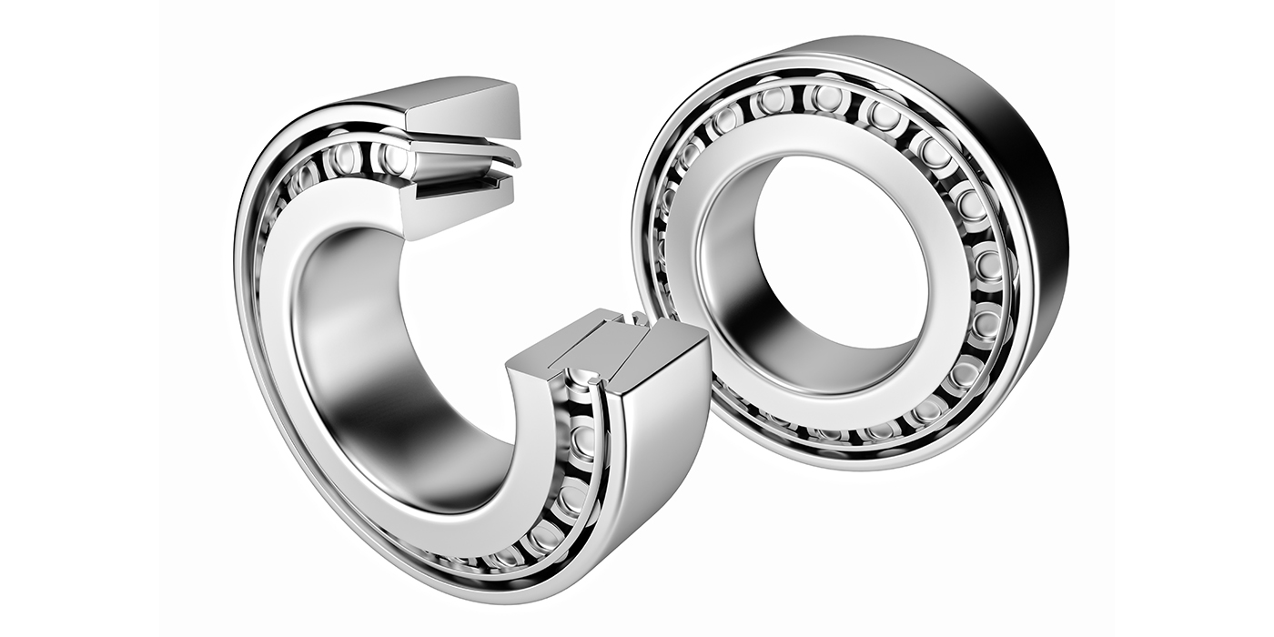
For technicians, the higher resolution wheel speed sensors on modern vehicles can do more than just speed. These sensors can detect small movements of the wheels to aid in both convenience, mechanical and safety systems.
The typical driver complaint will be that they have lights on and a warning message in the instrument cluster. They may even complain features they rely on are no longer working.
So what is the diagnostic strategy? We have covered what is the condition. The cause of a wheel speed sensor code or complaint can be mechanical or electrical.
Start With the Codes
Wheel speed sensor codes come in two flavors – “electrical circuit” codes and “erratic” codes caused by conditions where the ABS module can’t rationalize the outputs of a given wheel speed sensor. Circuit codes for opens and shorts are easy to understand electrically. Codes for erratic performance can be caused by the physical relationship between the wheel bearing encoder ring and the wheel speed sensor. These codes are generated when the module processing the signal can’t rationalize the changes in speed when compared to the other wheels, or to the laws of physics. All wheel speed sensor codes are just the starting points of a diagnosis and not a reason to order a part.
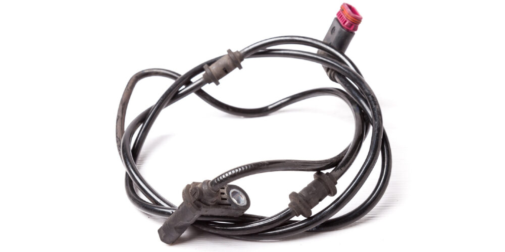
If the codes are electrical in nature, you need to confirm the resistive value of the wheel speed sensor, which should be between 1,000 and 2,500 ohms (top tip: check a known-good wheel speed sensor on the opposite side of the vehicle to get the exact value). Next, examine the integrity of the wiring. In addition, measure the output of the voltage or the presence of a bias voltage to confirm the operation of the module.
As stated earlier, erratic wheel speed sensor codes are set because the module can’t rationalize the output of a sensor. If the module sees a dropout of the signal from the sensor, it would literally translate into the vehicle stopping in inches and then accelerating back to that speed in a few inches. The software controlling the ABS knows this is not possible, so it sets a code.
Electrical Operation
There are two “types” of sensors generally found on the modern car – the passive speed sensor and the active speed sensor. They both perform the same function, but work entirely different. The passive speed sensor uses a magnet with fine copper wire wrapped around it to create its own alternating magnetic field. The polarity changes from positive to negative as the tone ring passes by the magnetic field. This frequency changes with wheel speed.
The newer active sensor uses a digital signal created by the ABS controller. This type of sensor uses a Hall effect or a variable reluctance signal with a square wave pattern. The sensor consists of two wires; one is used as the positive DC voltage from the controller and the other lead as the return (ground) to it. The advantages of the active speed sensors are their ability to read more accurately at slow speeds than the passive speed sensors. They don’t have to self-generate the needed voltage by the spinning action of the wheel. Also, since these sensors use a DC voltage, they can detect not only the speed of the wheel, but the direction of travel.
Active speed sensors or “Magneto Resistive Sensors” consist of two parallel resistors and a magnetic material located at a precise distance from a permanent magnet. The resistors are about 1.4k ohms each, however if you were to measure the resistance at the wire ends you would probably see 5 to 6 mega ohms. That’s because you are reading the resistance values of not only the resistors but the magnetic material inside the sensor. These parallel resistors work together to create the voltage changes you’ll see on your lab scope as the tone wheel or encoder ring passes by the internal magnet. The tone wheel (if flattened out) looks like the square wave pattern it creates. As the high part of the tone wheel’s tooth is near the sensor, a higher voltage is created while the opposite is done when the lower part of the tone wheel is near the sensor, even though it is close to battery voltage at the sensor.
A test light consists of a ground lead, a bulb (resistance) and the positive end, which is basically the same thing the sensor has internally minus the magnets. If you try stabbing a test light on the positive lead to the sensor, the computer sees that as a possible short to ground. Meaning, it thinks your test light is the sensor because the return voltage on the ground side of the sensor has drastically changed. In fact, in most of these ABS systems, if you do “short” the lead, the processor shuts that sensor off (0.0v) until the next key cycle. This way it avoids any harm coming to the internal circuits of the processor. But, if you continued to check the circuit without turning off the key, you’d end up back at the processor and more than likely come to the conclusion the processor is bad.
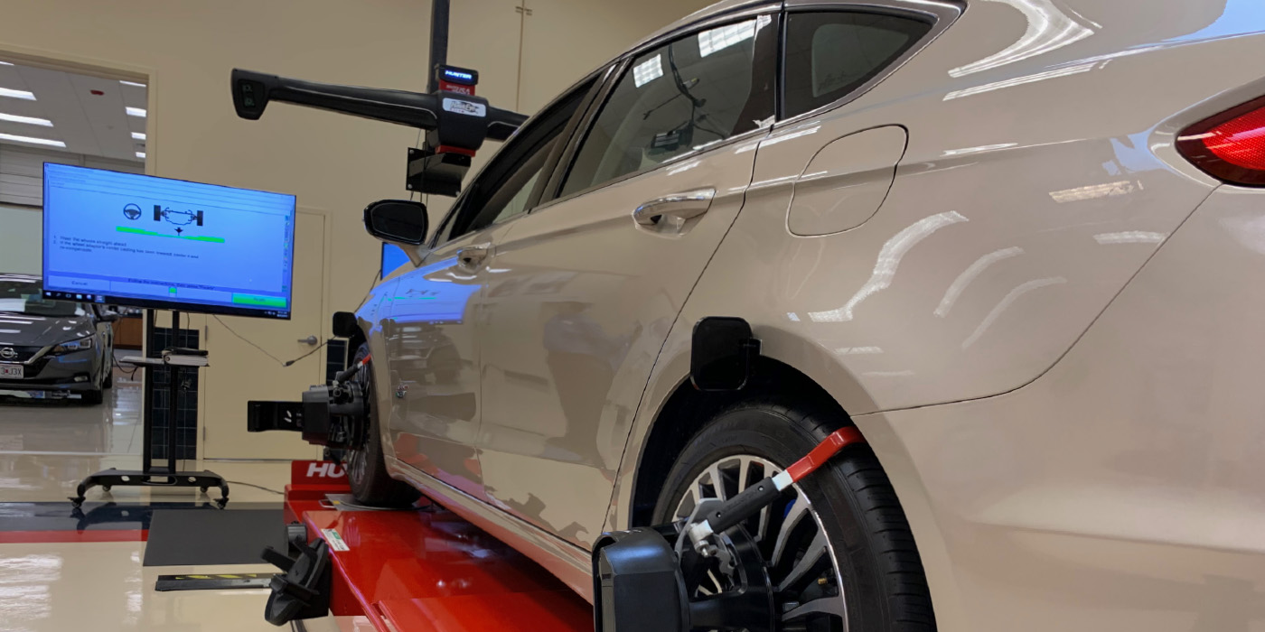
Scoping Wheel Bearings
Using an oscilloscope or scope can measure more than just the output of the signal. Testing with a scope can show the health of the circuit with the wheel speed sensor on one end and the module at the other.
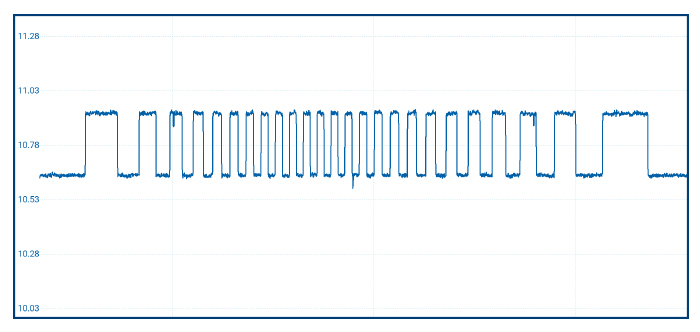
An active wheel speed sensor takes voltage from the ABS module (ranging from 8 to 12 volts) and changes the voltage signal by only 0.6 to 1.2 volts. The square wave’s peaks and valleys show the alternating polarity magnets in the encoder ring passing by the tip of the sensor. The faster the magnets pass by, the greater the frequency of the waveform, which is then translated into wheel speed by the ABS module. While this explanation might be oversimplified, it is enough knowledge to interpret the waveform.
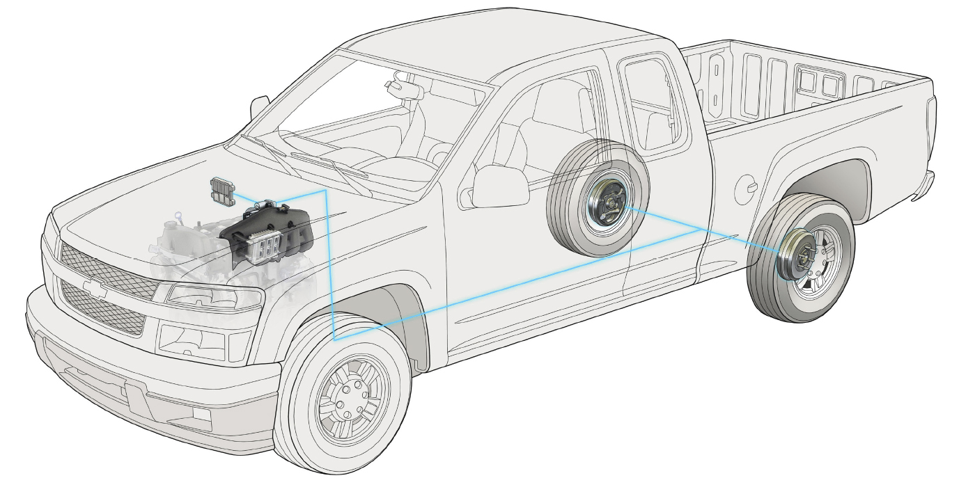
Before you connect a scope, you need to better understand the circuit and bias voltage. The ABS module supplies voltage to the wheel speed sensor. The overall current levels of a wheel speed sensor circuit are low, but if the circuit is shorted to power or ground, there is potential to do damage to the circuitry in the module measuring small changes in voltage. There are no fuses in the wheel speed sensor circuit to protect the module. The module protects itself by sending out a low-voltage signal for a millisecond when it is first turned on and performs a self-check.
If the circuit is compromised by an open or short, the increased or decreased resistance will cause the voltage to drop or exceed specifications. If the readings from the bias voltage tests are correct, the module provides voltage to the circuit for operation. If the readings are not in the predicted range, the module will not supply power, and will set a code and deactivate the ABS and stability control systems.
Bias voltage tests also work to detect opens in the circuit. This is why if a wheel speed sensor is disconnected it will cut power and set a code. When the untrained technician does not see power at the sensor, he may think the module is defective and replace the module.
To read the voltage with the system on, you will have to back-probe a connector or use a bypass harness to clear the code from the ABS module to test the circuit.
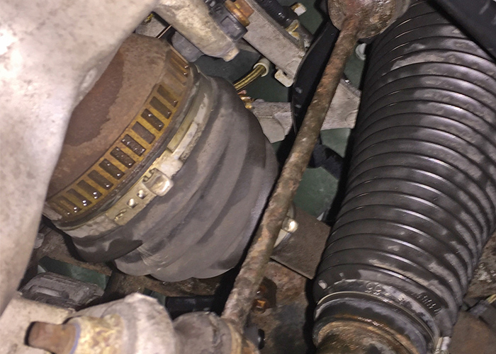
When a scope is attached, you will have to adjust your voltage scale and cursors to see the 0.6 to 1.2 volt changes in the 5-12 volt range. The waveform should be clean and consistent. Missing peaks and valleys can indicate damage to the encoder ring. In some cases, the magnets of the encoder ring will attract metallic debris, causing the waveform to skip between peaks and generate codes for an erratic signal.
A low current amp clamp can be used to check active wheel speed circuits. It will not be able to see with the same resolution as a voltage test, but it can confirm if the module is providing power and even a bias voltage signal. The only problem is finding a section of the harness where the two wires are divided in the wheel well.