Torque Sensor
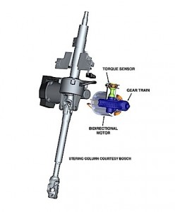
The torque sensor performs the same function as the torsion bar and spool valve in a hydraulic system. The electronic sensor uses a torsion sensor in the same manner as in the spool valve. There are different types of electronic torque sensors, and they are classified as contact and non-contact types.
The non-contact sensor uses a magnetic rotor with alternating pole pieces attached to the torsion bar. A sensor monitors the twist of the torsion bar by measuring the change in magnetic flux generated in the vanes located on the stator rings. A contact-type sensor uses a wiper attached to the torsion bar and voltage divider attached to the rotating bridge circuit on the steering shaft to measure the twist of the torsion bar. The change in resistance is used to measure the torque applied to the steering shaft.
EPS/ESC Interconnection
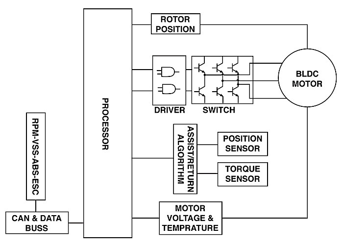
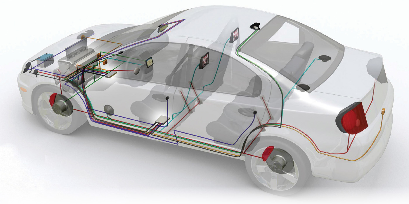
The electric power steering is connected to the vehicle data bus(s) for chassis and powertrain communications as an integral part of the Controlled Area Network (CAN). The data bus supplies vehicle speed, engine speed, ABS and ESC information. On-Board Diagnostics (OBD-II) has established generic failure codes. A failure of the torque sensor would most likely set a Diagnostic Trouble Code (DTC), U0130: Lost Communication with Steering Effort Control Module, and U0131: Lost Communication With Power Steering Control Module. The DTCs C0460 and C0545 for Lack of Power Assist, and C0472 and C0473 for Steering Wheel Speed Sensor Signal Voltage Low or High will also apply. Other DTCs will be specific to the manufacturer of a particular steering gear. If the vehicle has a Driver Information Center, it can supply information about a system by displaying the message “POWER STEERING” and turning on the service-soon light.
The following is taken from General Motors Bulletin Number 06-02-32-002B: “The purpose of this bulletin is to inform technicians of normal operating characteristics of the electric power steering system (EPS) when the steering wheel is turned in either direction for an extended period of time. When the steering wheel is turned to its maximum rotation, the power steering control module (PSCM) will command the maximum amount of current to the EPS motor. If the steering wheel is held in this position for an extended period of time, the PSCM will go into overload protection mode to avoid system thermal damage. In this mode, the PSCM will limit the amount of current commanded to the EPS motor, which reduces steering assist levels. If the PSCM detects a high system temperature and the overload protection mode is invoked, DTC C0176 ‘System Thermal Error’ may be set. On some models, DTC C0476 “Electric Steering Motor Circuit Range/Performance” may also be set. These DTCs indicate normal PSCM action (reduced steering assist) to prevent thermal damage to power steering system components.”
New technology will continue to modify the components and operation of existing systems. Steer-by-wire or brake-by-wire could be the next step with this technology, bringing more systems integration.
Diagnostics will require an examination of the total integrated system to determine the root cause of a component or sensor failure. Wiring harness routing and Electromagnetic Interference can influence low voltage sensor inputs. Connector integrity, moisture and corrosion will be part of any system failure.

