Understanding Electric Power Steering Systems
Electric power steering, or EPS, is more energy efficient than hydraulic systems and does not provide assist until it receives driver input. The steering wheel position sensor and applied torque sensor are attached to the steering shaft, and the inputs from these sensors are used by the ESC for braking to individual wheels by the ABS. Another feature of electric power steering is that it can operate the vehicle’s steering gear independently from driver input, allowing the electric power steering to perform a self-parking operation based on optical inputs to a controller that would operate the EPS. There are differences in the hydraulic and electric assist that will affect the driver’s and technician’s understanding of the component and its integration into the ESC and self-park system. For example, an electric power steering system will maintain assist if the engine stalls while the vehicle is in motion. If the electric power steering shuts down while the engine is running and the vehicle is in motion, a driver could lose control, as the loss of assist is not expected.
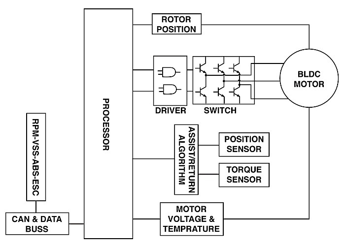
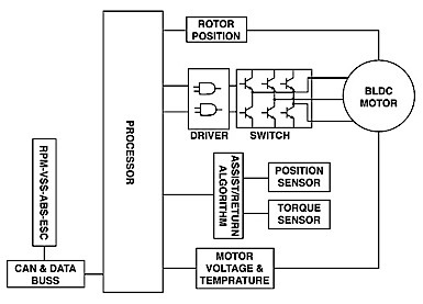
EPS Electronic Components Controller
The primary purpose of the electric power steering controller is to provide motor control. The controller processor output drives the three pairs of transistors that control the rotation of the motor. Input to the processor comes from the torque sensor and steering wheel speed and position sensor. Other processor inputs inclusive to motor operation are rotor position, motor voltage and temperature. The controller also has adaptive memory and diagnostics.
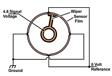
Position and Speed Sensor
The steering wheel sensor will provide input for both speed and position. It has four voltage divider circuits and a wiper. The voltage dividers are constructed of a resistive material on a film powered by a 5-volt reference to make four 90-degree sensing elements. The wiper has a contact that rides on the resistive film and supplies the output signal to the controller. The signal ranges from 0.5 to 4.5 volts, with a plus or minus 0.3 volts. For example: The sensor produces 0.2 to 4.8 volts when the steering wheel is rotated 90 degrees. Then, the sensor produces 4.8 to 0.2 volts for the next 90 degrees of steering wheel rotation in the same direction. When the steering wheel has been rotated 360 degrees, the voltage will have gone from 0.2 to 4.8 volts and 4.8 to 0.2 volts, and then from 0.2 to 4.8 volts and 4.8 to 0.2 volts in a constant rising and falling voltage. Failure of the steering wheel sensor can cause a shutdown of assist.