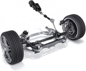
Measuring the position angle, rate of turn and force of the steering wheel is critical for Electronic Stability Control (ESC) systems. Scan tools call these Steering Angle Sensors (SAS) and typically display the information in degrees.
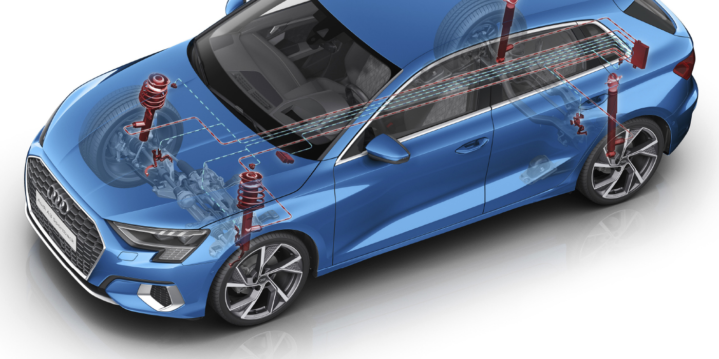
The SAS is typically part of a sensor cluster behind the steering wheel. The sensor cluster will have more than one steering position sensor, and some sensors consist of three sensors for redundancy and to confirm the data from the SAS. It’s important for the ABS/ESC module to receive two signals to confirm the steering wheel’s position, and these signals are often out of phase with each other.
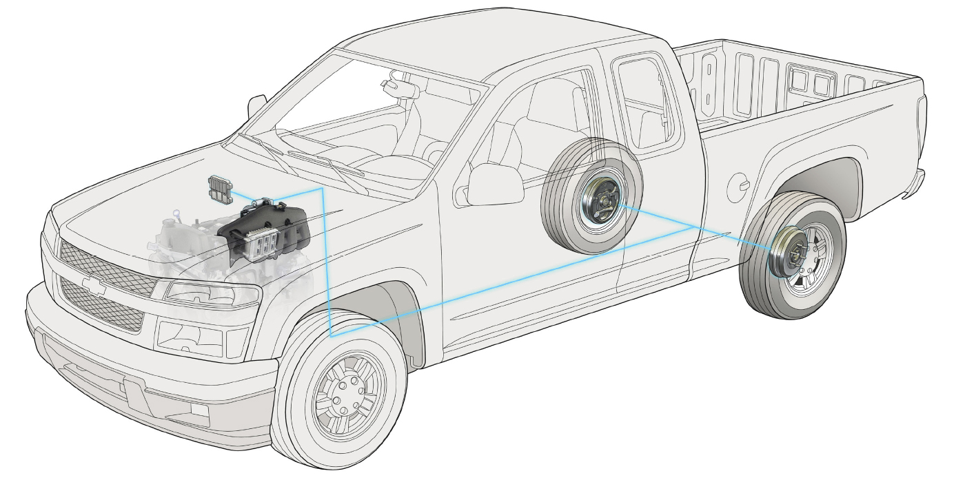
 Some SAS clusters and sensor modules connect to the Controller Area Network (CAN) bus, which is a high-speed serial data network that communicates in binary language to other modules or nodes. When you connect your scan tool to a vehicle, it becomes a node on a network. High-speed CAN buses, like GM LAN, use just two wires per module or node to communicate vast amounts of data. This means that a node, like an SAS module, needs to interpret and create signals that can be understood by the other modules on the bus.
The SAS module can connect directly to the ABS/ESC module on a CAN bus or it can be part of the overall CAN network, in a loop that connects various modules on the vehicle.
 Sifting through data
The best way to test modules on a high-speed CAN bus is with a scan tool. Most tools look at the data directly, but some scan tools may not be able to look at the datastream directly for a SAS signal because of software issues with the tool.
If you are in this situation, observe how the actuation of a sensor, switch or component can change activity on the data bus.
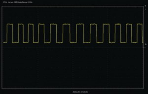
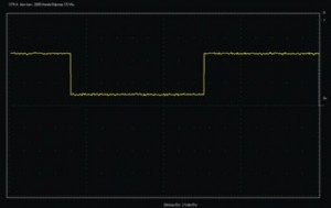 All CAN bus modules have power and two high-speed CAN wires. One wire toggles the voltage between 1.5- and 2.5-volts, and the other wire will toggle the voltages between 2.5- and 3.5-volts. Serial data buses toggle the voltages on the network to produce the 1s and 0s of binary language, and this voltage toggling communicates information and commands.
A scope connected between chassis ground and the bus wires in the OBD II DLC looking at the voltage can see packets of data being communicated on the bus.
On a direct-type SAS CAN sensor, you can see the sensors communicating with the ABS/ESC module as the wheel is turned. It’s impossible to tell what is being communicated, but it is possible to see if they are communicating.
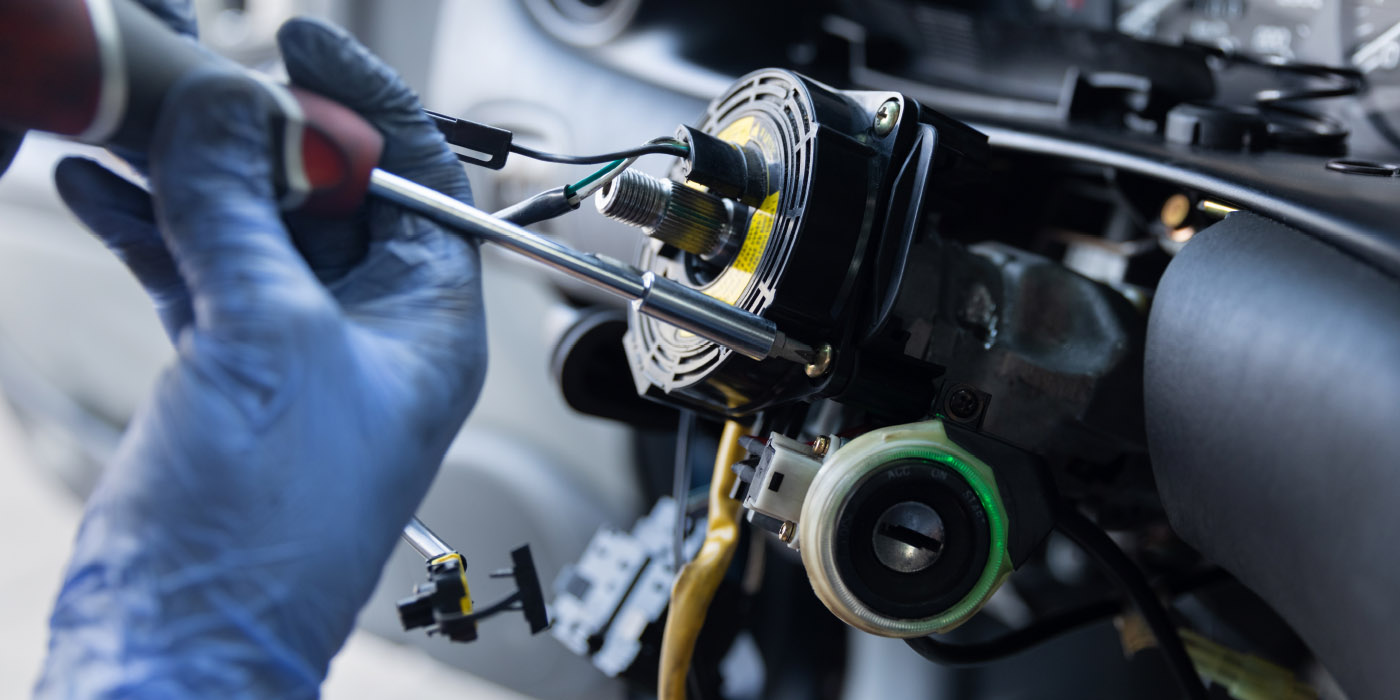
On some vehicles, the SAS sensor cluster is part of a module that may include functions for the turn signals, steering wheel, audio controls and wipers. This module is not a box, but part of the column and might have multiple CAN lines coming out of it. Often, the SAS cluster cannot be replaced on its own, instead requiring replacement of the entire unit.
Resetting Steering Angle Sensors
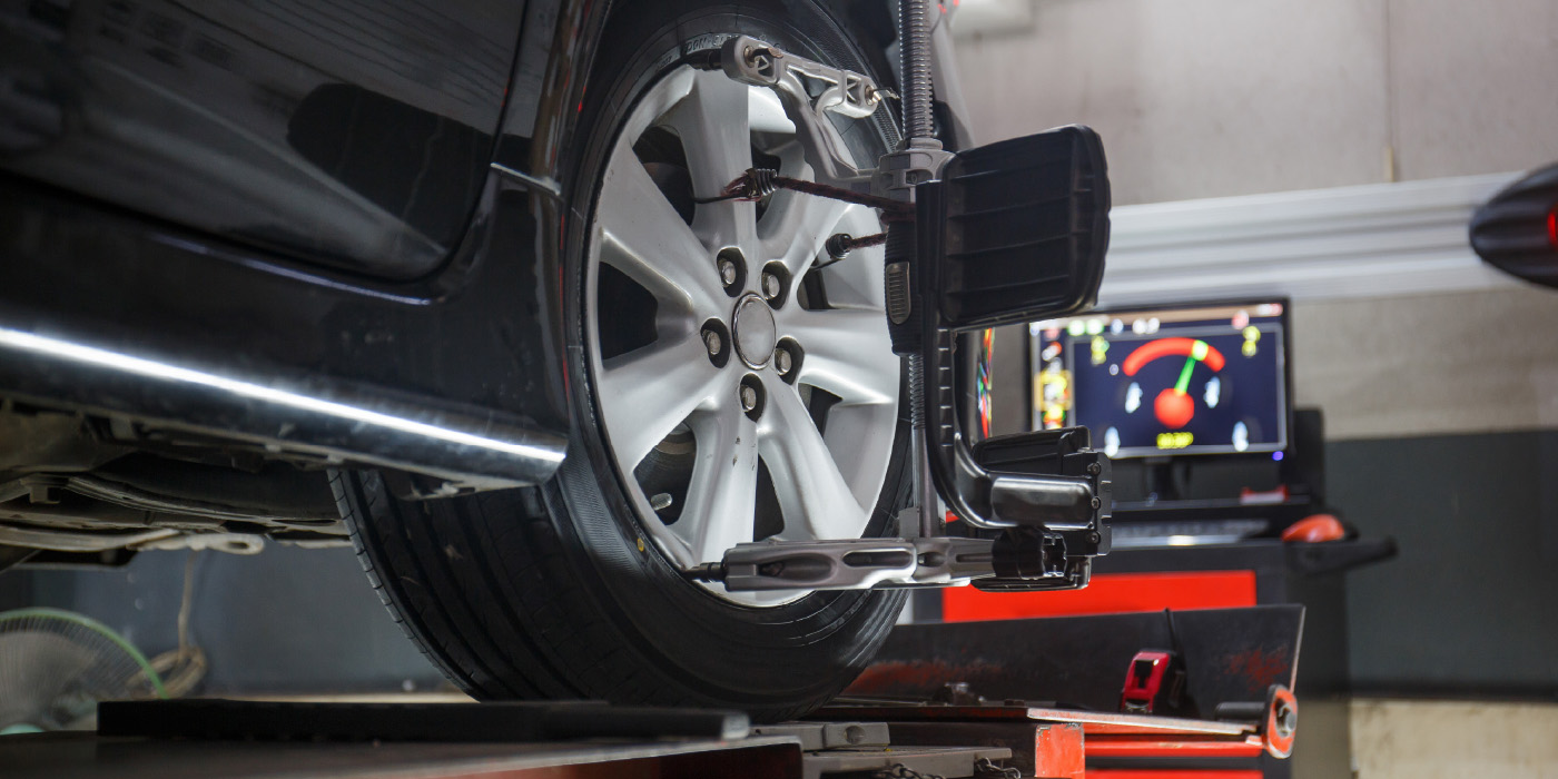
Many vehicles require that the SAS is reset or recalibrated after performing an alignment or replacing parts in the steering system. There are three types of reset procedures:
• First, some systems self-calibrate on their own.
• Second, some vehicles require specific wires or grounded or buttons that need to be pressed.
• Third, some systems require recalibration with a scan tool.
Even if the SAS is out of calibration, most vehicles can sense if it’s traveling in a straight line. If the angle is far enough out of range, it might set a trouble code and disable the ESC system.
Self-Calibration. On some Chrysler vehicles, recalibrating the sensor after an alignment or a dead battery is just a matter of turning the wheels lock-to-lock, centering the wheel and cycling the key.
This “auto learn” is becoming more common on newer vehicles.
 Scan Tool Steering Angle Sensor Reset. There are many options for scan tools to reset the SAS — some tools are even integrated into an alignment system.
After the reset is completed with the scan tool, the tool may advise you to go lock-to-lock with the steering wheel.
Tip: Perform lock-to-lock on every reset. Even if the lock-to-lock procedure is not performed, the data from the sensor will still say 0º. If the lock-to-lock procedure is not performed, the sensor may read 0º when the wheel is turned. This is not the fault of the scan tool. After a test drive, the scan tool is reading -540º. This is what happens when you do not move it lock-to-lock.
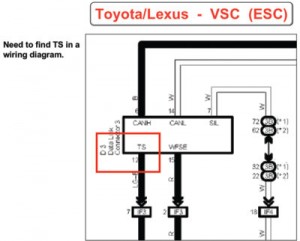
Jumper Wire SAS Reset (Toyota/Lexus)
Most Toyota vehicles have a process to reset the SAS called “zero-point calibration.” This process has been used for Toyota vehicles for more than a decade. The TSB for this procedure can be found under brake system TSBs and not steering TSBs.
While performing the zero-point calibration, do not tilt, move or shake the vehicle. The vehicle must remain in a stationary condition throughout the entire process. Be sure to perform the procedure on a level surface with an inclination of less than 1%.
Procedure
1. If the vehicle is equipped with A/T, ensure that the shift lever is in the “P” range and the parking brake is applied. If the vehicle is equipped with an M/T, ensure that the parking brake is applied.
2. Turn the ignition switch on.
3. Using SST 09843–18040 (jumper wire), repeat a cycle of short and open between terminals TS and CG of the DLC (pins 4 and 12) four times or more within eight seconds (refer to the specific vehicle EWD for TS and CG pin location in the DLC3).
4. Verify that the VSC indicator light is lit, indicating the recorded zero point is erased.
5. Turn the ignition switch off.
6. Be sure terminals TS and CG of the DLC3 are disconnected.
7. Turn the ignition switch on.
8. Check that the VSC warning light goes off about 15 seconds after the ignition switch is turned on.
9. After ensuring that the VSC warning light remains off for 2 seconds, turn the ignition switch off.
10. Connect terminals TS and CG of DLC3 using SST 09843–18040.
11. Turn ignition switch on.
12. After turning the ignition switch on, check that the VSC warning light is lit for about 4 seconds and then starts to quickly blink at 0.13 second intervals.
13. After ensuring the VSC warning light blinks for two seconds, turn the ignition switch off.
14. Remove the SST from terminals TS and CG of DLC3.
15. Drive the vehicle for at least five minutes to confirm zero-point calibration is complete.
If viewing Diagnostic Tester Data List after the repair, the SAS may remain at 1150º until the vehicle reaches 28 mph. This is a normal condition until the learned values of the steering angle have been achieved.
 CASE STUDY: Resetting Steering Angle Sensors on 2007 Toyota FJ Cruiser
Most enhanced scan tools can perform an SAS, accelerometer and yaw rate sensor reset and let you observe data from the sensors.
To start the calibration, the tool will tell you to be parked on a level surface with the steering wheel straight. Some vehicles have other procedures in terms of key and shifter position.
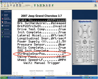
When the calibration is complete, the ABS and VSC lights will flash continuously. Look at the data for the SAS. The SAS will show 1150º, which is normal for a Toyota until the vehicle is driven above 28 mph and the steering has been turned lock-to-lock. The screen also shows the data from the lateral accelerometer. This FJ Cruiser has been jacked up by 10% on one side, which is why it’s reading at 0.1G. When the vehicle is dropped, the reading goes to 0.04G.
If you suspect a vehicle has a bad accelerometer, this test can reveal if the sensor is functioning without having to remove the center console. After the test drive, the steering angle is almost at zero.
When the wheel is turned to the left, the SAS reads 97º. When the steering is turned to the right, it displays -90º.