Electric power steering (EPS) has been around for more than 20 years. What was once a solution for small cars has turned into a “go to” steering assist for trucks, large sedans and EVs. The technology has made stop/start, hybrids and ADAS possible.
EPS has also improved over the years. Early systems suffered from overheating if the driver spent too much time making parking lot maneuvers. Many drivers complained that the system changed steering feel. Today’s systems have been refined and can even steer the vehicle independent of the driver.
What has changed the most is the connection the electric power steering control module has with the vehicle.
The Network
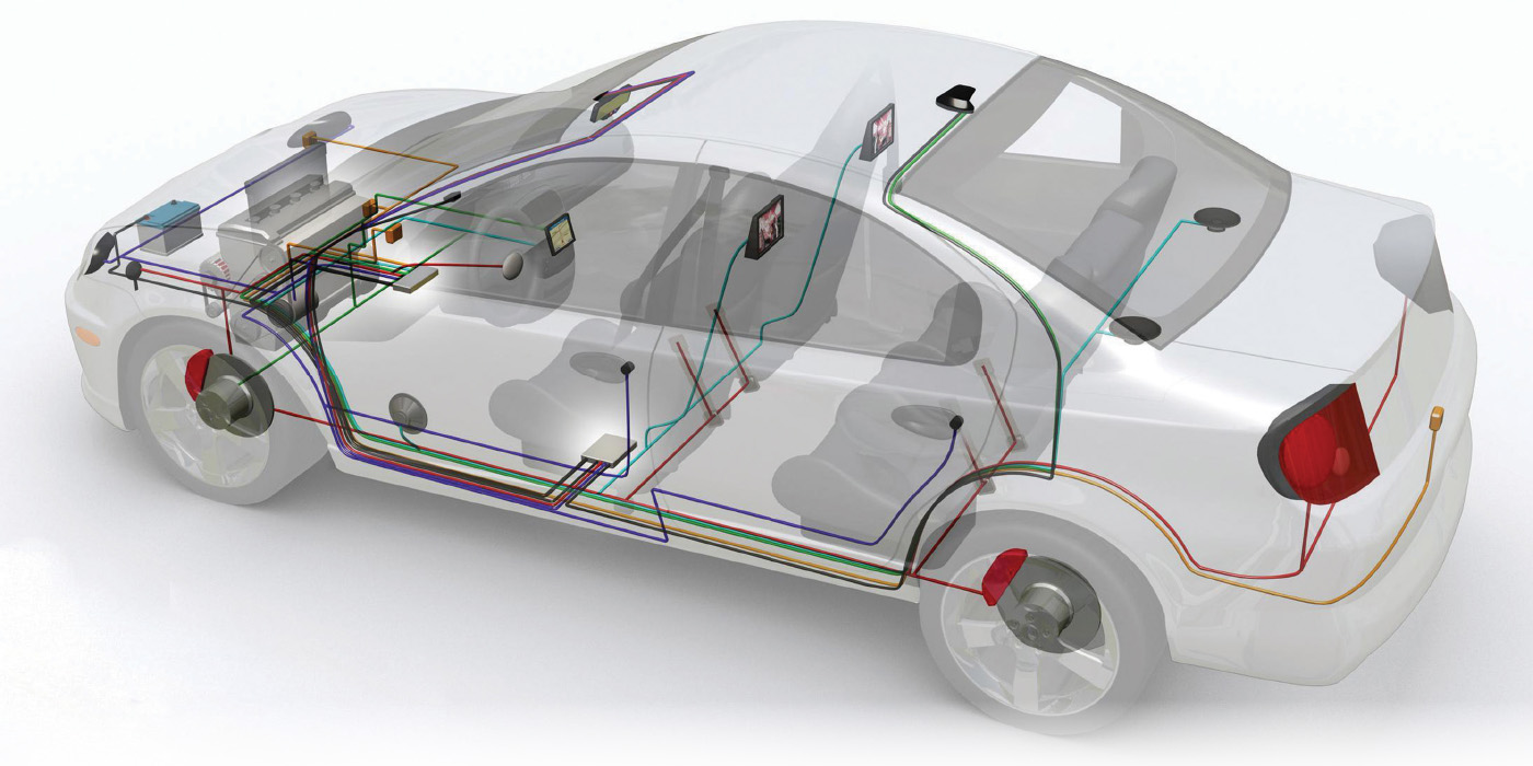
The EPS system is part of the Hi-Speed CAN bus on the vehicle. On this EPS network is the ECM for the engine and ABS/stability control system, and other modules like the body control module. This is why it is critical to pull up the wiring diagram that shows the map of the modules when doing your first diagnostic survey. Also, these other modules like to tell on each other if they are not adequately communicating or there is an issue with the CAN bus, like a short or open. This is why scanning all the modules as part of your first assessment of an EPS system can reveal more than just looking at the codes in one module. It is also essential to research the handshakes and self-diagnostic procedures some systems perform when the vehicle is started. In some cases, a connected module that is not performing correctly can cause the system to go into a fail-safe mode.
These modules share information for vehicle speed, steering angle and engine operation. Other information like ambient temperature is shared through gateway modules like the instrument cluster. The shared data can be used to solve mechanical problems like torque steer experienced by front-wheel-drive vehicles, and even pulls due to road crown or misaligned toe.
The ECM might receive the input from the throttle pedal, indicating the driver wants wide-open throttle while the vehicle is at a low speed. The information could be used by the power steering module to add specific levels of torque to counteract torque steer. The ABS module can also apply the brakes to steer the vehicle.
It also works the other way. The EPS module will communicate with the ECU to control engine speed when the alternator puts a load on the engine to power the motor on the rack. Many OEMs have issued updates to the software on the ECM and EPS modules to cure engine speed fluctuations. This is why on some models you need to reflash both the ECM and EPS modules. Many OEMs will issue TSBs about the updates.
Diagnostics
EPS systems can’t be fixed by throwing parts at the problem. The rack and module can be very expensive to replace. Steering angle and torque sensors are difficult to swap due to their position on the steering column.
The best approach to diagnose these systems is to look at the inputs, codes and the network through a scan tool, even before a physical inspection of the components. You need to look at the data from the sensors to make sure they are not giving erroneous information. Also, look at the other modules on the CAN bus to see if they are communicating. Missing pieces of data like vehicle speed or yaw can cause the system to go into a fail-safe mode.
Another feature of EPS is pull compensation. If you have a scan tool that can reset the pull compensation, you can use this feature to help diagnose mechanical and alignment problems.
Pull compensation has probably saved OEMs and dealers millions by eliminating owners from complaining about small “pulls” that cause the driver to add 2 to 5 degrees of steering input to keep the vehicle going straight down the road. Most of these pulls are entirely reasonable, but they can take dealerships hours in warranty labor to satisfy the customer. The pull compensation feature adds small amounts of assist to counter the normal forces. The extra angle in the steering wheel is still there, but the driver is applying very little force on the steering wheel.
Sensor Inputs
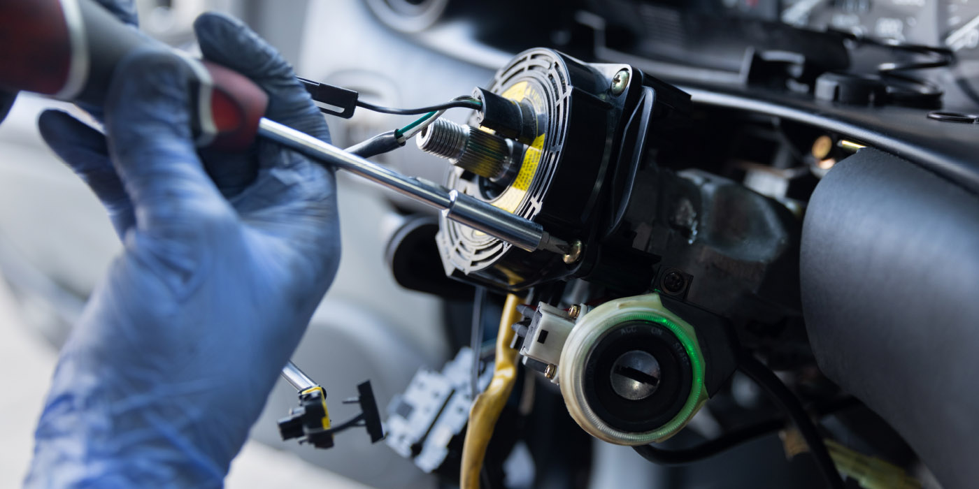
Measuring the steering wheel position angle and rate of turn provides critical info for the EPS system. The scan tool will typically display this information in degrees. The steering angle sensor (SAS) is part of a sensor cluster in the steering column. The sensor cluster will always have more than one steering position sensor.
Some sensor clusters have three sensors to confirm the data. Some SAS clusters and sensor modules are connected to a CAN bus. The SAS module or cluster can be connected directly to the ABS/ESC module on a CAN bus, or it can be part of the overall CAN Network in a loop that connects various modules in the vehicle.
The steering torque sensor measures the steering force applied by the driver and enables sensitive control of the electric steering support. It serves the same function as a spool valve in a hydraulic power steering system.
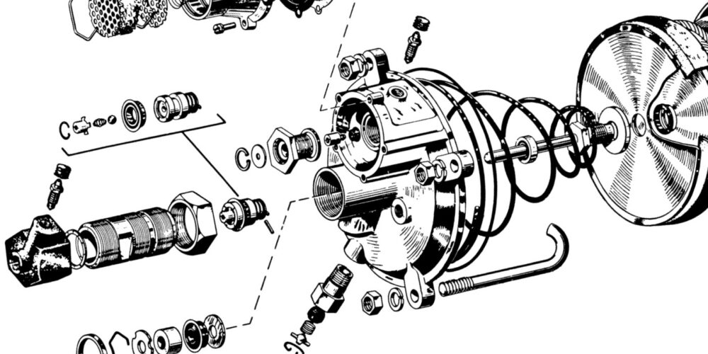
The Motor
EPS systems use an electric motor powered by a voltage signal to move the motor in both directions. The motor is brushless and has an operating voltage range of 9 to 16 volts.
The motor uses a rotational sensor that determines the position of the motor. On some systems, if the module is replaced or the toe has been changed, the end stops of the steering system must be learned so the motor does not push the rack past the maximum steering angle. This might be an additional step on top of calibrating the steering angle sensor.
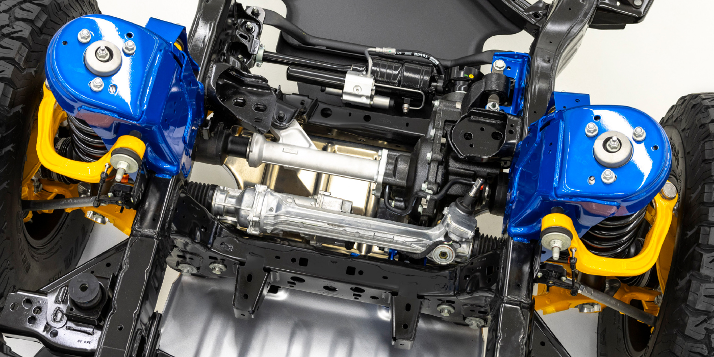
The motor can be connected to the steering rack or column. Today, more vehicles are using motors that are mounted to the base of the steering gear on the rack. The motor can connect to the rack using a screw-like connection or, in some cases, a high-strength belt.
The motor is not serviceable on most systems. The lash for the gears or the tension for the belt is set at the factory. Also, removing the motor from the rack might prevent you from getting your core charge back.
EPS Modules
An EPS module is more than just a circuit board and connectors in an aluminum box. The module contains the drivers, signal generators and MOSFET switches that power and control the electric motor.
The module also includes a current monitor circuit that measures the amps the motor is using. The current monitor and other inputs determine the temperature of the motor using an algorithm that even factors in the ambient temperatures.
If the system detects a condition that could cause the motor to overheat, the module will reduce the amount of current going to the motor. The system might go into a fail-safe mode, generate a DTC and alert the driver with a warning light or message.