Some 2005 – 2015 model year Tacoma vehicles with applicable suspension have a different coil spring diameter. This may lead to a lateral force applied to the support plate upon reassembly of the front shock absorber with coil spring assembly. This may cause the inner rubber sleeve of the support plate to pull out when spring tension is released and the support plate to tilt.
Use the following procedure to reduce the chances of the inner rubber sleeve of the strut front suspension support sub-assembly from tearing. NOTE: Apply a thin coat of a lithium-based grease to the shock absorber rod where it contacts the inner rubber sleeve on the support plate. Do NOT lift the vehicle too high without the shock absorber rod nut. The shock absorber rod nut could pull out of the front suspension support sub-assembly due to spring tension under vehicle load.
1. Refer to service information for the correct procedures according to model and year. Some Tacomas have different shock and spring specifications.
2. While following the repair procedure, it is important to note the lateral force direction of the spring applied to the support plate and shock absorber rod. The support plate and shock rod need to be perpendicular to avoid the inner rubber sleeve from pulling out when the tension is released.
3. Reinstall the front shock absorber with coil spring assembly into the vehicle using the original shock mount nuts. Torque to the specified value.
4. Lower the vehicle to resting position ride height, but leave the lift arms set under the vehicle.
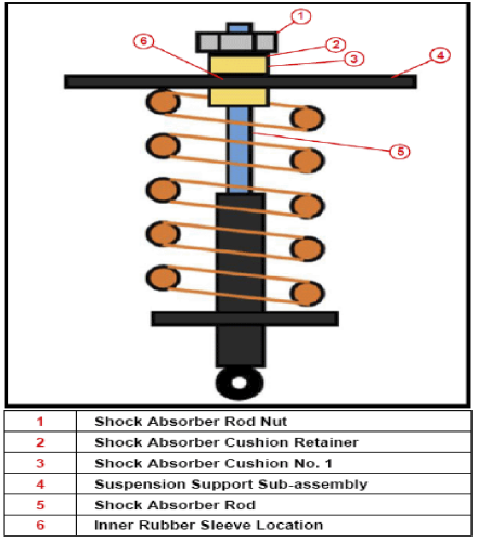
5. Remove the shock absorber rod nut, front shock absorber cushion retainer, and front shock absorber cushion No. 1 to expose the top of the front suspension support subassembly.
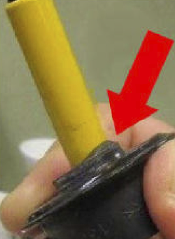
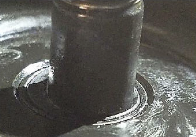
6. Visually inspect the inner rubber sleeve of the front suspension support sub-assembly. The inner rubber sleeve of the front suspension support sub-assembly will likely be deformed as shown on page 57.
7. Reinstall the shock absorber rod nut for safety. Secure the shock absorber rod nut with only a few turns, ensuring contact with at least 3-4 threads.
8. Bump the lift controls slowly and raise the vehicle approximately no more than 1/2 inch. Do not lift too high. Small increments are important as the inner sleeve will hit a point where it pulls down below the surface. This will require starting over from initial reassembly to properly correct this condition.
9. Push the inner rubber sleeve down into the front suspension support sub-assembly and make sure it is as flush as possible. Perform a “fingernail test” to confirm proper fit. There should be minimal difference in height between the inner rubber sleeve and front suspension support sub-assembly.
10. Once the inner rubber sleeve is flush, remove the shock absorber rod nut from the shock absorber rod and make sure no tension is being applied. Do not lower or raise to reinstall the front shock absorber cushion No. 1 as the inner rubber sleeve can move.
11. Reinstall the front shock absorber cushion No. 1, front shock absorber cushion retainer, and shock absorber rod nut. Make sure to torque the shock absorber rod nut to the specifications in the repair manual.
12. Lower the vehicle and perform a road test to confirm the condition is no longer present.
Courtesy of Mitchell1