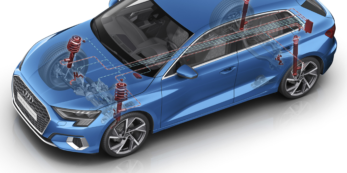
Twenty years ago, automotive engineers were trying to make the case for the 42-volt electrical system. Engineers thought that 42 volts would allow for smaller electrical motors, with smaller wires. They also predicted more and more loads were going to be put on the electrical system like electric power steering, electric suspensions and heated windshields.
So, what happened? The most challenging thing with 42 volts was turning the power off and on and the relays were the most difficult to engineer. But, over the past 20 years, the OEMs have also gotten better about managing power and the loads on the alternator, and distributing the power to where it is needed. These refinements are the reason why you see more vehicles with electric power steering.
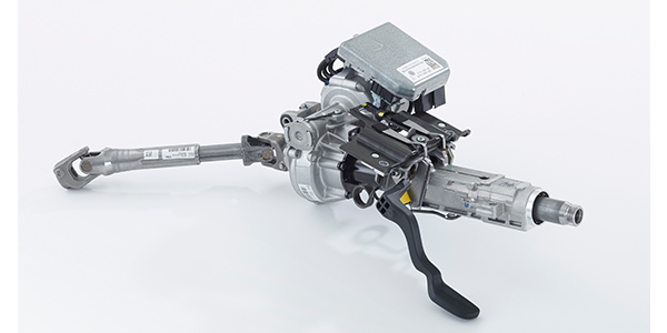
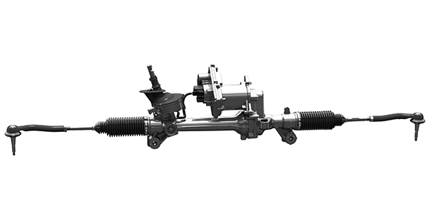
Electric power steering has been around for more than 30 years. The first systems used a conventional hydraulic rack that was mated to a hydraulic pump. They were used on rear-engine sports cars in the 1980s. The problem on those vehicles was the distance between the steering rack and engine. In the early 2000s, electric power steering — with electric motors mounted to the rack or column — was the choice for small cars and newly introduced hybrids. Electric power steering is now being used on vehicles ranging from full-size pickups to electric cars.
The Basics
No matter how the steering is assisted, issues with the mechanical steering and suspension components could lead you to misdiagnose the power steering system. Isolating the problem is a lot better than going on a hunch that the power steering component is malfunctioning.
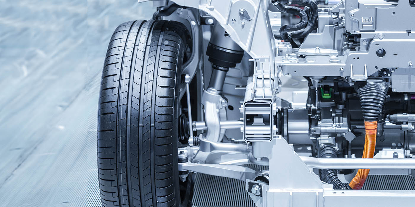
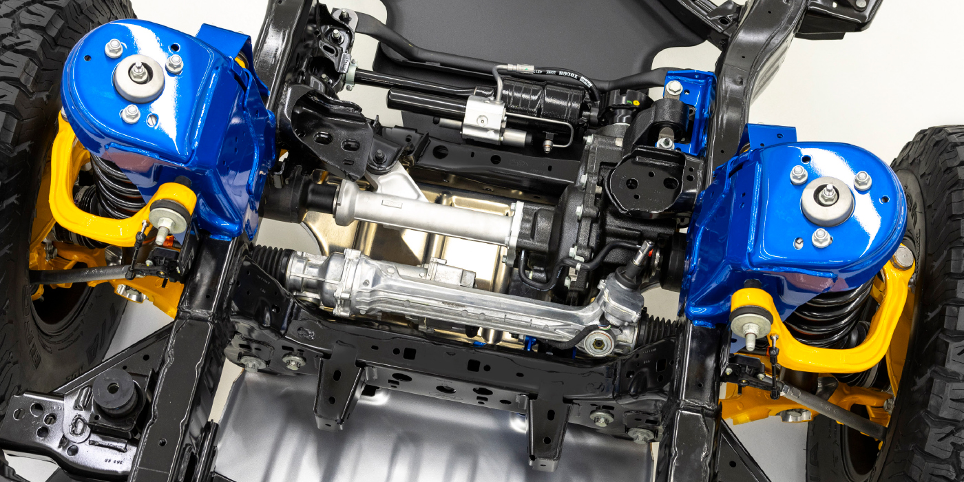
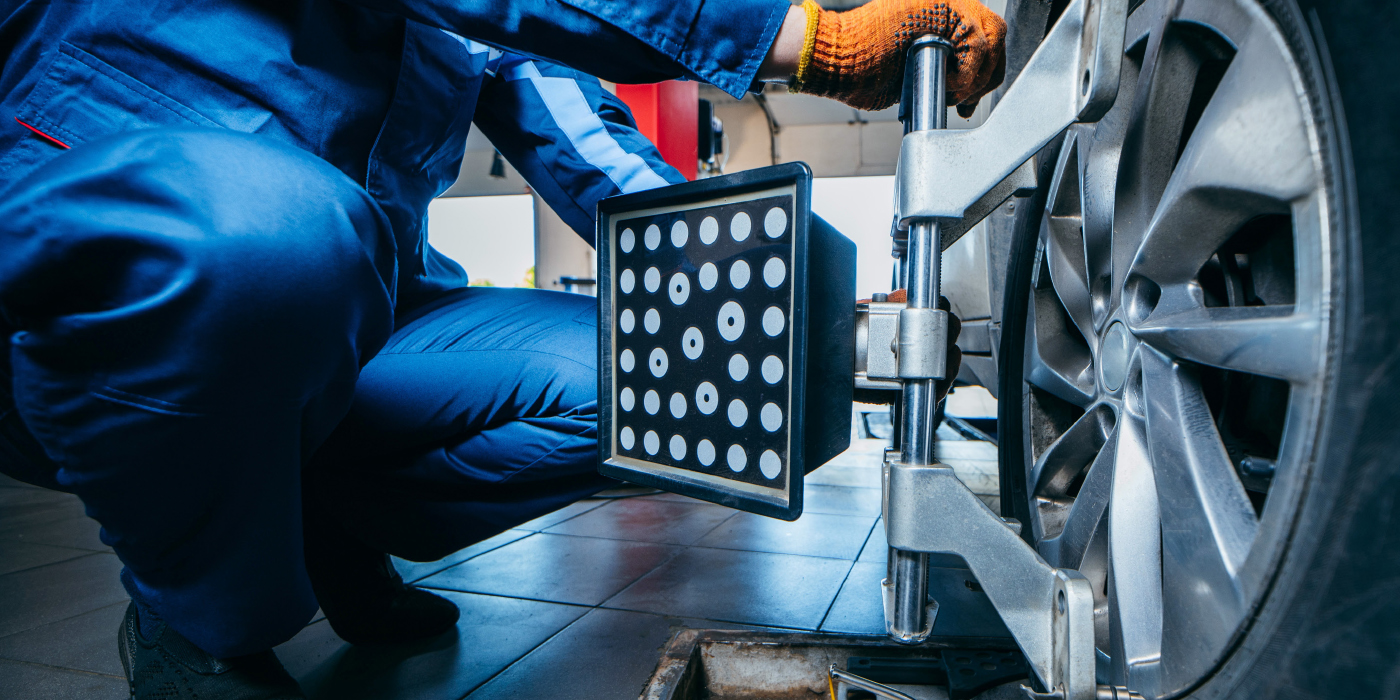
The chassis alignment is critical with any power steering system. Caster, camber and the steering included angle (SAI) can change the effort required to change the direction of the vehicle. Many vehicles now have different steering geometries to take advantage of electric power steering’s ability to prevent torque steer, bump steer and improve the return-to-center characteristics of the wheel.
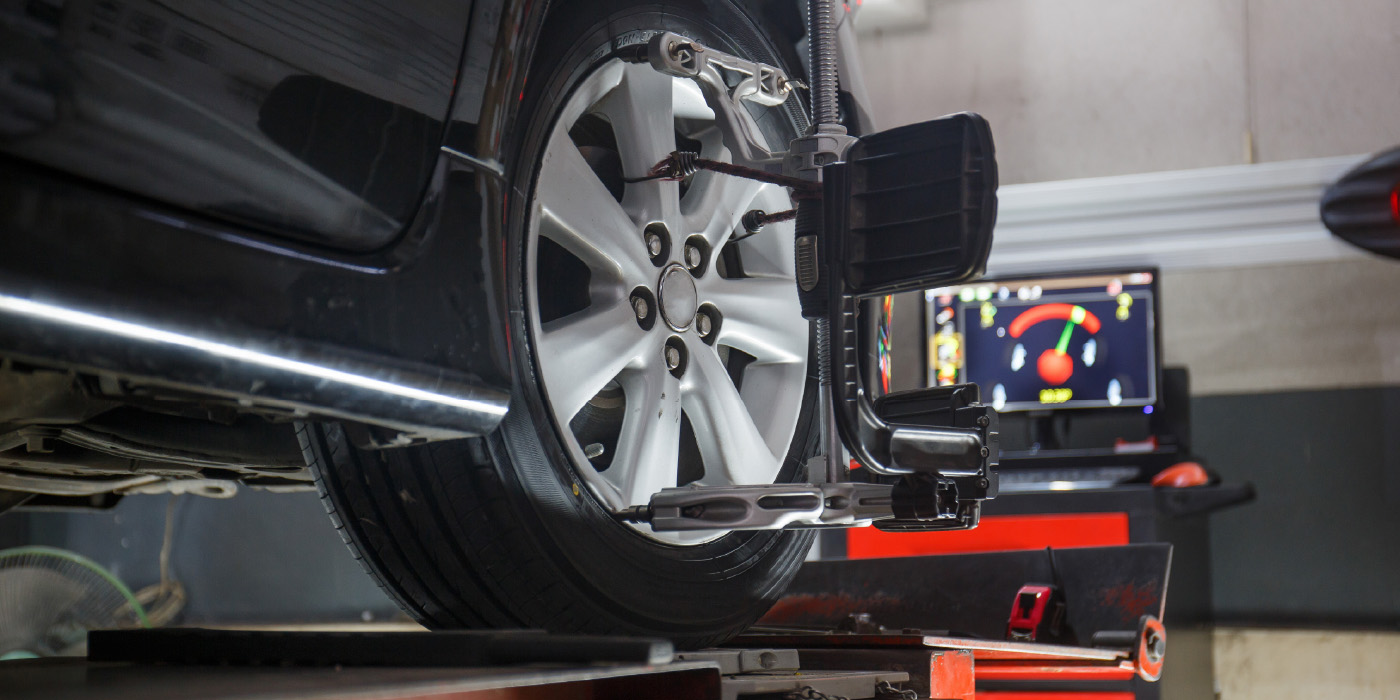
Many customer complaints will not be accompanied by a code or MIL light, as most of these complaints are mechanical. One diagnostic method is disabling the electric power steering system while it is on the lift and turning the steering wheel to lock. This will help to isolate the electrical part from the mechanical components. It can be done by removing a fuse or with a scan tool on some makes and models.
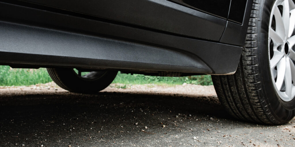
In some cases, increased friction in the steering is not the fault of the power steering system. Ball joints can become stiff or even bind and cause changes in steering effort. It may also be a bent strut rod that is causing changes in steering feel from lock to lock for the customer.
Another trick is to disconnect the outer tie rods. By disconnecting the steering and suspension system, you can isolate issues like play and binding. If possible, perform this check on an alignment rack the turn and slip plates so the suspension is loaded.
One complaint from a customer you may hear is that the steering suddenly kicks back after a bump is hit. This is typically due to play in the mounts that hold the rack to the vehicle, or the electric power steering module to the steering intermediate shaft.
How is it Connected?
Most electric power steering system modules are on the high-speed CAN network with the engine control, ABS and transmission control modules. Some vehicles will also include the body control module and other modules that are critical to the safety of the vehicle. These modules share a lot of data to make sure the driver does not notice when the electric power steering is working.
For example, if the power steering motor is assisting the driver, the engine control module will increase the throttle plate angle as the alternator puts a load on the engine. The ABS system uses inputs from the steering module for steering angle, wheel speed and torque.
No system operates alone. If a module is not talking or missing data from a sensor, the other modules will set codes in different modules on the network in the form of communication codes and codes that indicate a sensor is out of range.
How is it Wired?
Systems can use both brushless and brushed direct current (DC) motors. The power to the motor is controlled by a series of Mosfet transistor switches that can switch high current off and on quickly. You can look at the voltage on a scope going to the motor, but its reference waveforms are challenging to find.
Just about every electric power steering system has a circuit that measures current in the motor circuit. By measuring the current, the steering module knows if there is a short, open or high resistance. Also, the system can calculate the temperature of the motor. If the calculated temperature is too high, the system will go into a safe or passive mode until the motor has cooled down.
The torque sensor measures the amount of force being applied through the steering wheel and feedback from the rack. These types of sensors have two position sensor rings at either end of a shaft or device that flexes tiny amounts. If the torque sensor is damaged, it can cause the system to go into fault or safe mode. On some models, if the torque sensor has a small alignment problem the wheel can twitch in the straight-ahead position.
Electric power steering adds a lot more functionality to the vehicle. Some vehicles are using it for lane departure systems and self-parking systems. Some of these systems are out of warranty and coming to your shop.