Applicable Models:
2003-’07 Cadillac CTS
2004-’08 Cadillac SRX
2005-’08 Cadillac STS
2006-’08 Pontiac Solstice
2007-’08 Saturn SKY
Drivers of certain General Motors vehicles may complain of fluid seeping or leaking from the rear axle. To correct, install a rear differential hose, clamps and a new metal differential vent following this repair procedure.
Note: Do not replace the rear differential axle assembly.
Repair Procedure
Review safety procedures in ALLDATA Repair before beginning.
CTS, SRX and STS models
1. Place the vehicle in neutral. Raise and support the vehicle.
2. Determine if the leak is coming from the rear axle differential vent — if the leak is not coming from the axle vent, then do not proceed to the next step.
3. Remove the rear propeller shaft following factory or industry standard practices.
4. Place a jack stand under the rear axle assembly for support and remove the three rear axle bolts and nut.
5. Lower the rear axle enough to gain access to the rear differential vent, located at the top of the axle.
6. Pry the top of the metal rear differential vent cap off.
7. Discard the old vent cap and spring.
8. Obtain a hose that is 9.50 mm (3/8 in) inside diameter by 30.50 cm (12 in) long and is rubber low fuel pressure/oil resistant or equivalent, a new differential vent and two hose clamps.
9. Assemble the new vent onto the hose with a clamp.
10. Tighten the clamp.
11. Install the second clamp onto the hose.
12. Attach the other end of the rear differential hose assembly to the axle vent.
13. Position the second clamp around the rear axle vent and hose.
14. Tighten the second clamp.
15. Raise the axle assembly back into the vehicle.
16. Install the three axle bolts and nut.
17. Tighten the bolts to 129 ft.-lbs (175 Nm). Remove the jack stand.
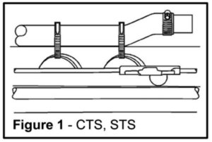
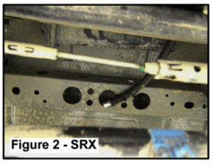
18. To prevent a rattle from occurring, make sure the vent cap is not touching anything when tied down. Tie strap the hose and vent assembly. The CTS and STS should be strapped to the rear crossmember frame (Fig. 1). The SRX should be strapped to the underbody sheet metal reinforcement (Fig. 2).
19. An over-filled differential will cause fluid to seep out of the rear axle vent. Check the differential fluid level.
20. Clean off any axle fluid residue with a suitable brake cleaner.
21. Install the rear propeller shaft back into the vehicle.
Solstice and SKY models
Some 2006 Pontiac Solstice models may have a plastic-style rear differential vent in the axle assembly. The plastic vent will need to be replaced with the new style metal vent.
1. Raise and support the vehicle. Determine if the leak is coming from the rear axle differential vent — if the leak is not coming from the axle vent, then do not proceed to the next step.
2. Remove the exhaust system.
3. Remove the driveline tunnel closet panel for vehicles equipped with a turbo following factory or industry standard practices.
4. Place a jack stand under the rear axle assembly and remove the rear axle bolts.
5. Lower the axle assembly to gain access to the vent.
6. Pry the top of the metal rear differential vent cap off, and discard the old vent cap and spring.
7. Obtain a hose that is 9.50 mm (3/8 in) inside diameter by 30.50 cm (12 in) long and is rubber low fuel pressure/oil resistant or equivalent, a new differential vent and two hose clamps.
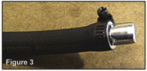
Note: If the clamp is not positioned correctly, the vent may fall off.
8. Assemble the new vent onto the hose and clamp the outer shoulder of the vent (Fig. 3).
9. Tighten the clamp.
10. Install the second clamp onto the hose.
11. Attach the other end of the rear differential hose assembly to the axle vent.
12. Position the second clamp around the shoulder of the rear axle vent and hose as you did previously.
13. Tighten the second clamp.
14. Raise the axle assembly back into the vehicle.
15. Install the axle bolts.
16. Tighten the bolts to 129 ft.-lbs (175 Nm). Remove the jack stand.
17. To prevent a rattle from occurring, make sure the vent cap is not touching anything when tied down.
18. Tie strap the hose and vent assembly to the left body cross brace, refer to Fig. 1.
19. Over-filling the differential will cause axle fluid to seep out of the rear axle vent. Check the differential fluid level.
20. Clean off any axle fluid residue with a suitable brake cleaner solvent spray. Install the driveline tunnel closet panel if equipped with a turbo.
21. Install the exhaust system.
22. Drive the vehicle to confirm the repair.
Courtesy of Ed Dorowski, ALLDATA editor, and Jeff Webster, ALLDATA technical writer. ©2010 – 2014 ALLDATA LLC.