By Tom Purser, ALLDATA editor, and Jeff Webster, ALLDATA technical writer.
 Some Buick owners may complain about one or more of the following conditions:
- Service Engine Soon (SES), Anti-Lock Brake (ABS) or Traction Control System (TCS) lamp may be illuminated;
- A no-crank/no-start condition;
- Various intermittent I/P concerns;
- Shifter will not move out of Park (brake/transmission interlock solenoid inoperative); and/or
- Diagnostic Trouble Codes (DTCs) U1000, U1016, B1422, B2957 or B2958 may be set. Additional codes may be found due to this concern.
These conditions may be due to deformed or collapsed terminals in the Engine Wiring Junction Block (Underhood Bussed Electrical Center [UBEC]) connectors causing a poor connection. To correct the problem, follow the service procedure listed below.
Applicable Models: 2001-2004 Buick Century and Regal
 Correction
- Remove the Underhood Electrical Center/Engine Wiring Junction Block base assembly.
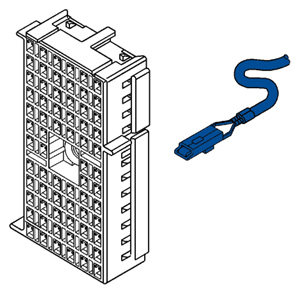
- Inspect all of the terminals in UBEC connectors C1, C2 and C3. Use Terminal Test Kit J 35616A in order to determine proper terminal tension (see Figure 1).
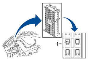
- If any of the terminals are visibly damaged/ deformed/collapsed (see 1 in Figure 3), go to the repair procedure in this bulletin.
- If all of the terminals are not damaged and proper connections can be made, perform the standard diagnostic procedures in the appropriate Service Manual.
Repair Procedure
Important: Refer to the Reference Guide in the Terminal Repair Kit (J 38125-C) for the proper removal and crimping tool and part replacement information for the 68-way (female) Metri-Pack 280 Series connector.
- Remove the Terminal Position Assurance (TPA) device from the connector (see Figure 2).
- Insert the proper removal tool into the front of the connector body in order to disengage the flexible lock under the damaged terminal(s).
- Gently pull on the wire to remove the terminal through the back of the connector.
- Cut the wire as close to the old terminal as possible.
- Strip 3/16” (5 mm) of insulation from the wire.
- Use the proper crimping tool and crimp a new terminal to the wire.
- Solder the crimp with rosin core solder.
- Insert the new terminal and wire into the back of the connector. Ensure the terminal is seated and the flexible lock is engaged.
- Install the Terminal Position Assurance (TPA) device into the connector.
- Install the Underhood Electrical Center/Engine Wiring Junction Block base assembly.
- Verify that the condition(s) has been corrected and DTCs are cleared.
For additional information, visit www.alldata.com.