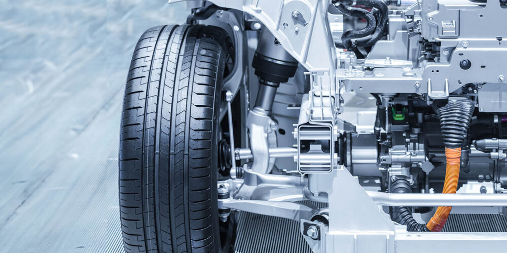
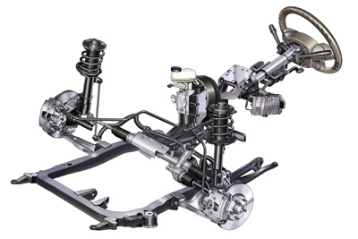
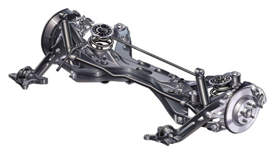
Front Suspension
The front suspension on the Malibu uses a MacPherson strut mounted to an aluminum knuckle and control arm. The ball joint is part of the control arm and cannot be replaced on its own. The ball joint has a wear specification of 3.18 mm (0.125 in).
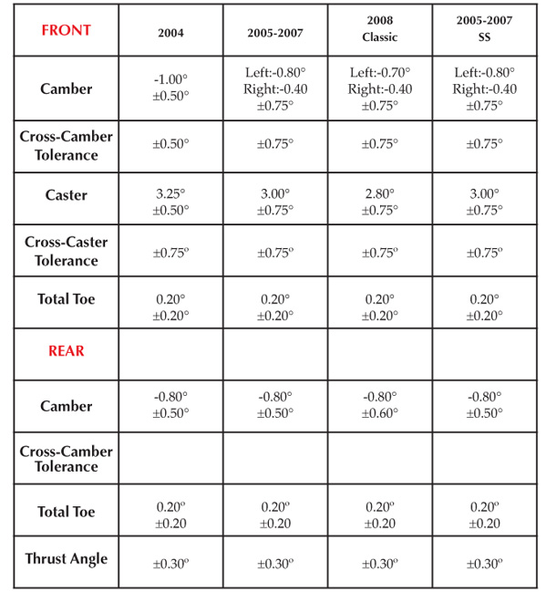
The front caster is not adjustable and the angle can be used to determine if there is suspension or body damage. Too much cross caster can cause the vehicle to pull in the direction of the side with the most negative caster.
Camber can be adjusted by either elongating the lower bolt holes in the strut or installing cam bolts in the lower strut mounting holes. Cam bolts can give an additional 1.75º of positive or negative camber.
If the vehicle is pulling in one direction, GM recommends adjusting the cross camber. The cross-camber is the difference between the left side camber and the right side camber (cross-camber = left camber – right camber). Positive cross-camber may cause the vehicle to pull to the left. For example, if the vehicle pulls to the left, adjust the cross-camber more negative and vice-versa. If the camber specification of either wheel is outside of specification after using this technique, look for other culprits like a pulling tire or damaged control arm affecting the caster angle.
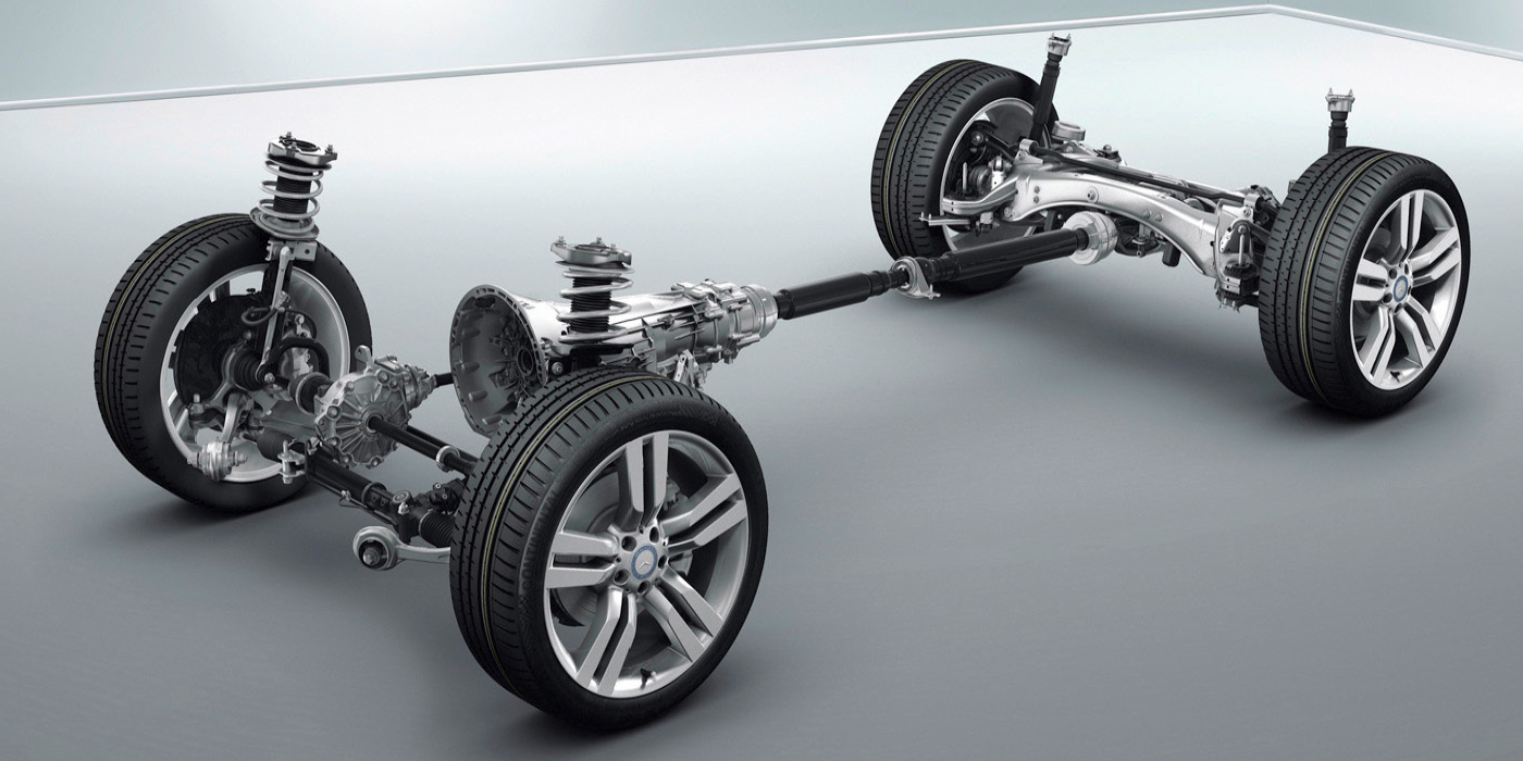
Rear Suspension
The four-link rear suspension is robust and has built-in adjustments for camber and toe.
To adjust the camber, loosen inner lower control arm cam-bolt nuts and adjust the cam-bolt to the correct specification.
To adjust the rear toe, loosen the inner toe link cam bolt and nuts. Rotate the cam bolt to the required toe specification settings.
The rear cams have a significant cross talk, so always recheck both angles after any adjustment of either cam.
Electric Power Steering
This generation of the Malibu was the first to get electric power steering (SS models have hydraulic power steering and do not require recalibration). The system does not use hydraulics to assist the driver. This system uses a brushless DC motor. The motor assists steering through a worm and reduction gear located on the steering column housing.
The Power Steering Control Module (PSCM) uses a combination of steering shaft torque sensor input, vehicle speed, calculated system temperature and steering tuning to determine the amount of steering assist. When the steering wheel is turned, the PSCM uses signal voltage from the steering shaft torque sensor to detect the amount of torque and steering direction being applied to the steering column shaft, and then commands the proper amount of current to the power steering motor.
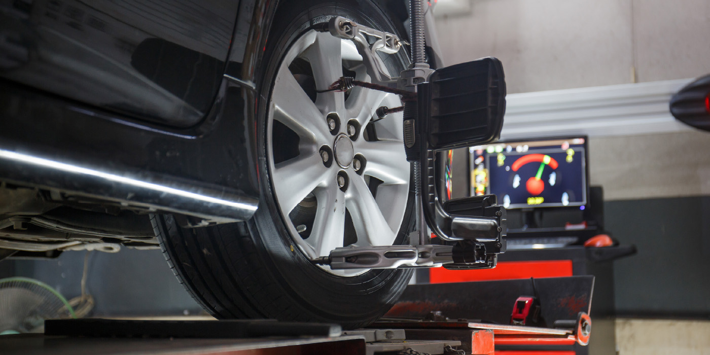
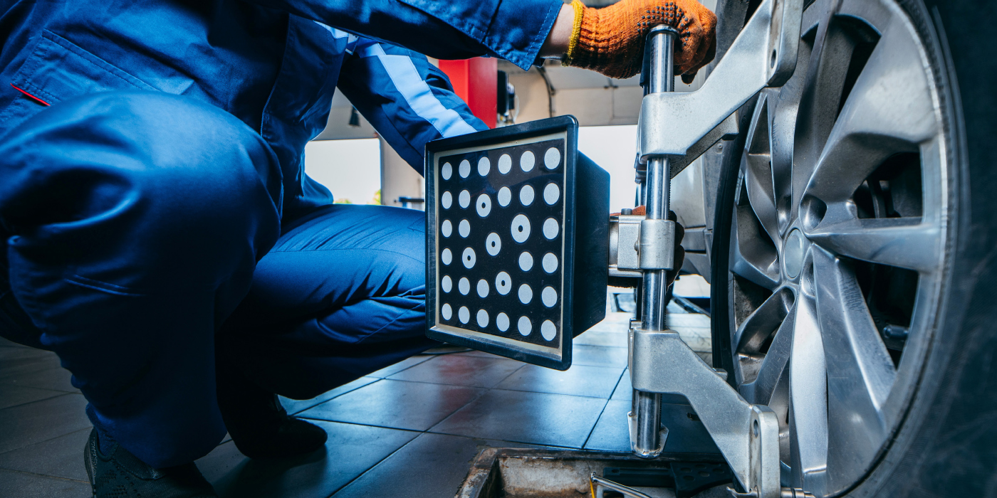
After an alignment is performed, it is required that the steering angle sensor and torque sensor are calibrated in order for the system to function properly. This is performed through the OBDII diagnostic connector. Failure to do this can result in damage to the system.
Only perform the steering position sensor and torque sensor recalibration procedure only after the tires, suspension and alignment specifications have been inspected and corrected. Failure to do so may result an unbalanced steering gear and lead to additional pull concerns.
Problem Areas
One area that has plagued the Malibus of this generation has been the steering intermediate shaft. To see the full TSB, look up TSB 06-02-32-007G that was issued on April 05, 2010.
Drivers may complain of a clunk noise heard and felt in the steering wheel while driving at slow speeds and turning. The clunk noise may appear to be directly in front of the driver. Hitting a bump while turning can produce the clunk noise.
Sometimes the noise may be duplicated when the vehicle is sitting still and the steering wheel is turned 90º in either direction before initially centering the steering wheel. The clunk noise may be caused by a slip/stick condition between the inner and outer components of the intermediate shaft.
Revised design intermediate shafts went into production in the 2009 model year and are the only design currently available through dealers since September 2008.
Since any model year vehicle could have had a second design shaft installed, it is critical to identify it before proceeding. The revised or second design shafts are painted black and the old style are bare metal.
In the unlikely event that the source of the noise is identified as a second design shaft with black painted tube, it must be replaced.
The revised design intermediate shafts will not tolerate any type of lubricant per the following instructions. Adding lube to the second design shafts will cause a clunk noise in a very short period of time.