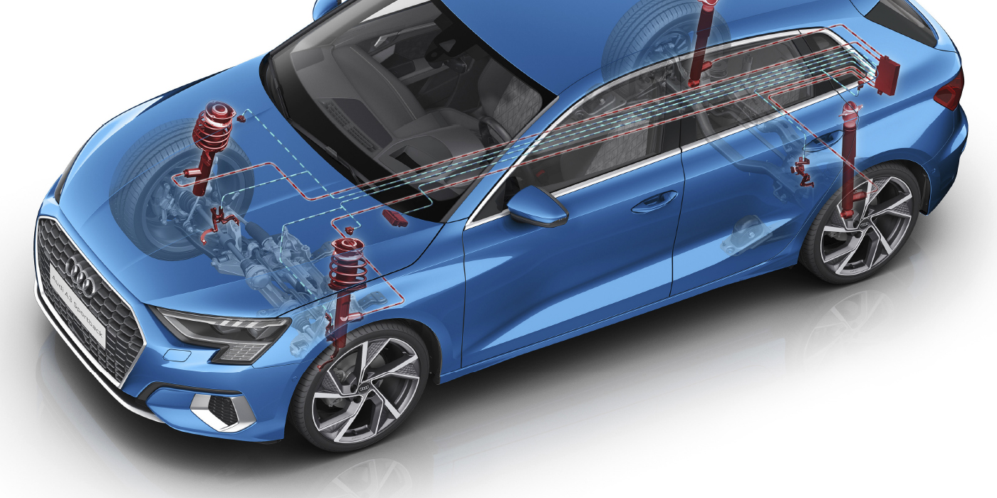
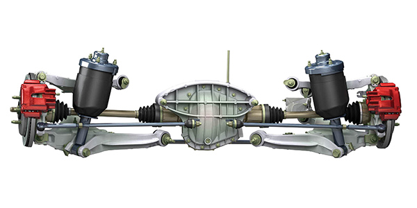
 The Ford Expedition air suspension does more than just lift and raise the vehicle. The system levels the vehicle under loads and when a trailer is attached. The system uses only two air bags on the rear axle, unlike previous models with air bags on all four corners. Also, unlike previous Expedition models, the rear suspension is independent. If the air suspension is malfunctioning, it will have a direct impact on tire wear.
Before starting any work, you need to disable the system through the message center. It is located on the instrument cluster and displays important information through a constant monitoring of vehicle systems. Select “display features” on the message center for a display of the status, proceeded by a brief chime.
When the driver elects to disable the air suspension system, the message center sends a message over the High Speed Controller Area Network (HS-CAN) bus to the air suspension module. Once the message is received, the air suspension module will take no further action to inflate or deflate the air springs. The system will default to ON when the ignition key is cycled.
1. Turn the ignition to the ON position, close all doors and clear warnings.
2. Select the SETUP control function on the message center.
3. Select the AIR SUSPENSION function to display the current status of the air suspension system.
4. Press the RESET control to turn the air suspension OFF or ON.
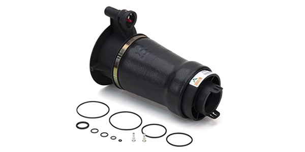
The air bag and shock absorber can be separated. Make sure you know the orientation of the upper mount and air spring before you take the assembly apart. To deflate the spring, remove the air line from the solenoid, remove the retaining clip and rotate the solenoid counter-clockwise. Air should rush out. The O-rings on the shaft and upper mount should always be replaced and lubricated with a silicone-based spray lubricant. These help to seal the unit from outside debris.
Operation
The system uses two ride height sensors mounted to the rear axle. The voltage output decreases (goes from high to low) as the suspension system raises the vehicle. The output voltage is between 0.5 and 4.5 volts. These signals are sent to the Vehicle Dynamics Module (VDM).
Testing these sensors can be done with a meter, scope or scan tool. With a meter, it is possible to observe changes in the voltage or resistance.
The air bags have solenoids mounted to the side that allow the bladder to either fill or compress. There is no air reservoir on this system.
When the key is in the ON position, the load-leveling feature automatically makes adjustments to the vehicle height so that the vehicle is always at target height and constant front-to-rear vehicle attitudes are maintained when loads change.
The system will remain active for 40 minutes after the ignition is turned off, allowing the system to deflate (vent) at any time, while allowing the system to inflate (pump) only once at the end of 40 minutes. This leaves the vehicle with a consistent stance if a load is removed or added from the rear.
The system also looks at vehicle speed, system voltage and even the ambient temperature to decide if an action should be taken. Also, problems with door switches and the power running boards can inhibit the air suspension from making a correction.
The system will set C- or chassis codes if the system notices abnormal behavior. These codes typically start with C17XX.
Calibration
Scan tools are essential for working on some systems. Some enhanced scan tools can observe PIDs for the air ride system like valve operation, modes and vehicle position. Some new GM vehicles have a calibration process for the ride control system.
The Expedition’s ride height and trim can be calibrated with a scan tool. Not calibrating the ride height can result in suspension and tire damage. To do this the vehicle must be on a level surface. The ride height is measured and the scan tool can vent or fill the correct bag.
Compressor Problems
The heart of an air ride system is the piston, piston ring and cylinder. Heat will hasten the failure of the piston ring. The system is dry and no lubricants protect the piston. The VDM control modules regulate when and how long the compressor will run to keep temperatures in a designated range to manage the heat by looking at ambient temperature and other factors.
The software controls the temperature of the compressor so it does not damage itself trying to inflate a leaking air bag. It can also change the characteristics of the air bag in response to how fast the vehicle is going, and if it is in sport or towing mode. But, most of all, it helps to filter out erroneous ride height readings so the best possible ride is achieved.
 When air is compressed, the water vapor contained in the air is condensed into a liquid that can damage not only the compressor, but also the valves. If there is no means of removing the water from the system, it will find its way to all parts of the system causing corrosion damage or freezing.
The Expedition’s compressor has a dryer that is connected to the compressor outlet and a connection to the air springs to absorb the water entering the system. It is the large black cylinder next to the motor.
The dryer contains a moisture-absorbing desiccant, such as silica gel. The desiccant can hold a given amount of water, but once the desiccant is saturated with water, it will allow water to pass into the system. The dryer should be replaced if an air bag is leaking or the compressor has failed.