An Electronic Power Steering (EPS) system’s advantage over a hydraulic system is if the engine stalls, you will still have steering assist. This advantage can also be a disadvantage if the system should shut down while the engine is running because if the engine stalls, you lose steering assist.
Figure 1
A driver unaware of this condition would become concerned if an electrical or electronic failure occurred while the engine was running, as the loss of assist would not be expected.
EPS systems eliminate the need for a pump, hoses and a drive belt connected to the engine using variable amounts of power. The configuration of an EPS system can allow the entire power assist system to be packaged on the rack and pinion steering gear or in the steering column.
The system does not provide assist until required by driver input. This means that there is no drag on the engine from either a power steering pump or alternator until it is really needed. Also, there is no hydraulic fluid, which is one less use for a petroleum product.
Figure 2
Brushless Application
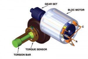
A typical EPS steering application uses a bidirectional brushless motor, sensors and electronic controller to provide steering assist. The motor will drive a gear that can be connected to the steering column shaft or the steering rack. Sensors located in the steering column measure two primary driver inputs — torque (steering effort) and steering wheel speed and position.
The steering wheel is referred to as a handwheel in the service information. The torque, speed and position inputs, along with the vehicle speed signal and other inputs, are interpreted in the electronic control module.
The controller processes the steering effort and handwheel position through a series of programs called algorithms for assist and return to produce the proper amount of polarity and current to the motor.
Other inputs that will affect assist and return are vehicle speed, engine speed and chassis control systems such as ABS and electronic stability control (ESC).
The brushless motor uses a permanent magnet rotor and three electromagnetic coils to propel the rotor. Most applications use a motor worm gear to drive the gear on the steering shaft or rack (Fig. 1).
The brushless bidirectional permanent magnet motor and gear perform the same function as the power cylinder in a hydraulic system.
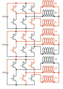
Pairs of six switching transistors are forward biased and move the rotor in a clockwise or counterclockwise direction. The pairs are A+ and C-; B+ and A-; C+ and B- (Fig. 2). The rotor direction is determined by the sequence in which voltage is applied to coil A, B or C and returned to ground through an attached pair. The sequence for clockwise is ABC and for counterclockwise it is CBA (Fig. 3).
Figure 3
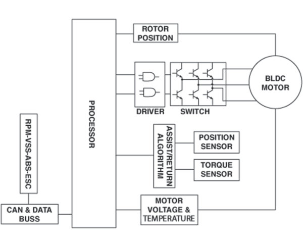
The primary purpose of the EPS controller is to provide motor control. The processor is the heart of the controller for input and output. Processor output drives the three pairs of transistors that control the rotation of the motor. Primary input to the processor comes from the torque sensor and handwheel speed and position sensor.
Other processor inputs include rotor position, motor voltage and temperature.
The processor also is an integral part of the controlled area network (CAN) and vehicle data buss for chassis and powertrain communications. This data buss supplies vehicle speed, engine speed, ABS and ESC information (Fig. 3). The controller has adaptive memory and diagnostics.
Figure 4
On-board diagnostics (OBD II) has established generic failure codes. A failure of the torque sensor would most likely set diagnostic trouble codes (DTC) U0130 — Lost Communication With Steering Effort Control Module — and U0131 — Lost Communication with Power Steering Control Module.
The torque sensor performs the same function as the torsion bar and spool valve in a hydraulic system. The electronic sensor uses a torsion bar in the same manner as in the spool valve.
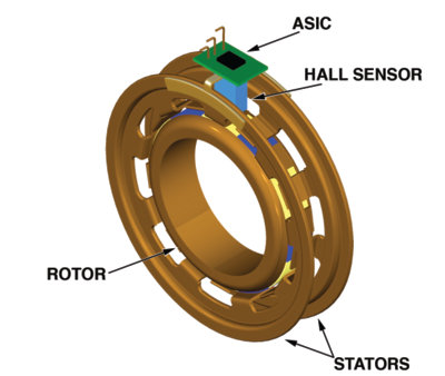
There are three different types of electronic torque sensors, and they are classified as contact and non-contact types. A non-contact sensor uses a magnetic rotor with alternating pole pieces and is attached to the torsion bar.
Hall-type sensors monitor the twist of the torsion bar by measuring the change in magnetic flux generated by its position to the vanes located on the sensor stator rings.
When the rotor moves, a change in magnetic flux will produce a signal to an analog sensing integrated circuit (ASIC) that will process the signal and send the information to the controller’s assist algorithm. ASIC is a description of what is generically called a “chip” (Fig. 4).
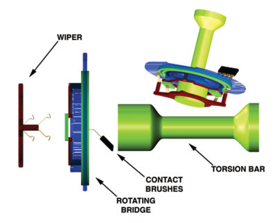
Figure 5
Contact-type torque sensors use a wiper attached to the torsion bar and voltage divider attached to the rotating bridge attached to the motor shaft to measure the twist of the torsion bar. The rotating bridge uses contact brushes that connect to the sensor housing and connector to receive power, ground and transfer the voltage signal to the controller (Fig. 5).
The electric steering system will retain the handwheel speed sensor (HWSS) for both speed and position. It will retain the four voltage divider circuits and a wiper.
The voltage dividers are constructed of a resistive material on a film powered by a five-volt reference to make four 90-degree sensing elements. The wiper has a contact that rides on the resistive film and supplies the output signal to the controller.
The signal ranges from 0.5 to 4.5 volts with a plus or minus 0.3 volts. For example: The sensor produces 0.2 to 4.8 volts when the steering wheel is rotated 90 degrees. Then the sensor produces 4.8 to 0.2 volts for the next 90 degrees of steering wheel rotation in the same direction.
When the steering wheel has been rotated 360 degrees, the voltage will have gone 0.2 to 4.8, 4.8 to 0.2, and 0.2 to 4.8, 4.8 to 0.2 volts in a constant rising and falling voltage.
New technology will continue to be introduced to existing systems. Throttle by wire is now a common feature on both domestic and import vehicles.
Andrew Markel is the director of content for Brake & Front End magazine. He has been with Babcox Media for 20 years. He is a technician and former service writer and holds several automotive certifications from ASE and aftermarket manufacturers. He can be reached at [email protected].
Published:
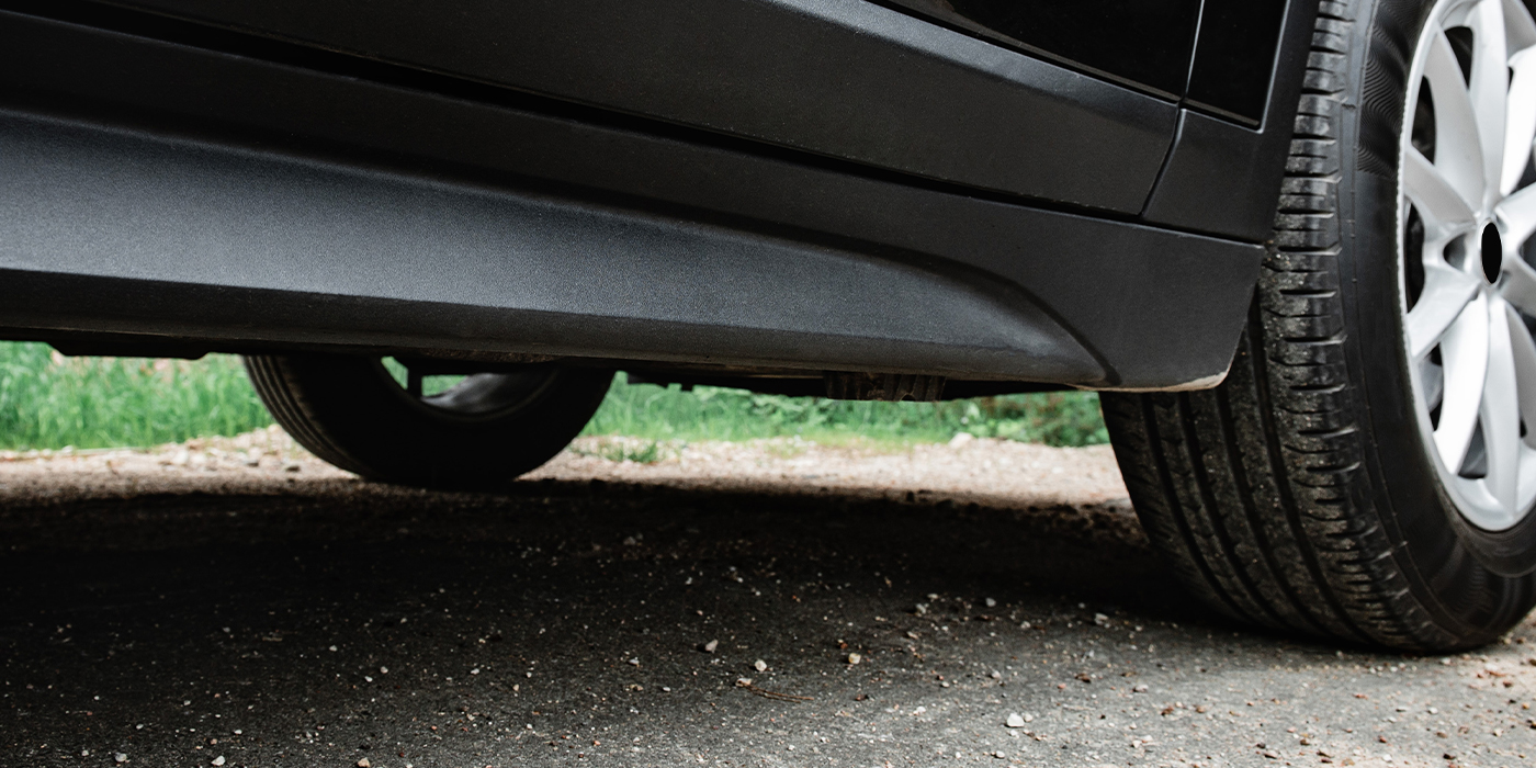
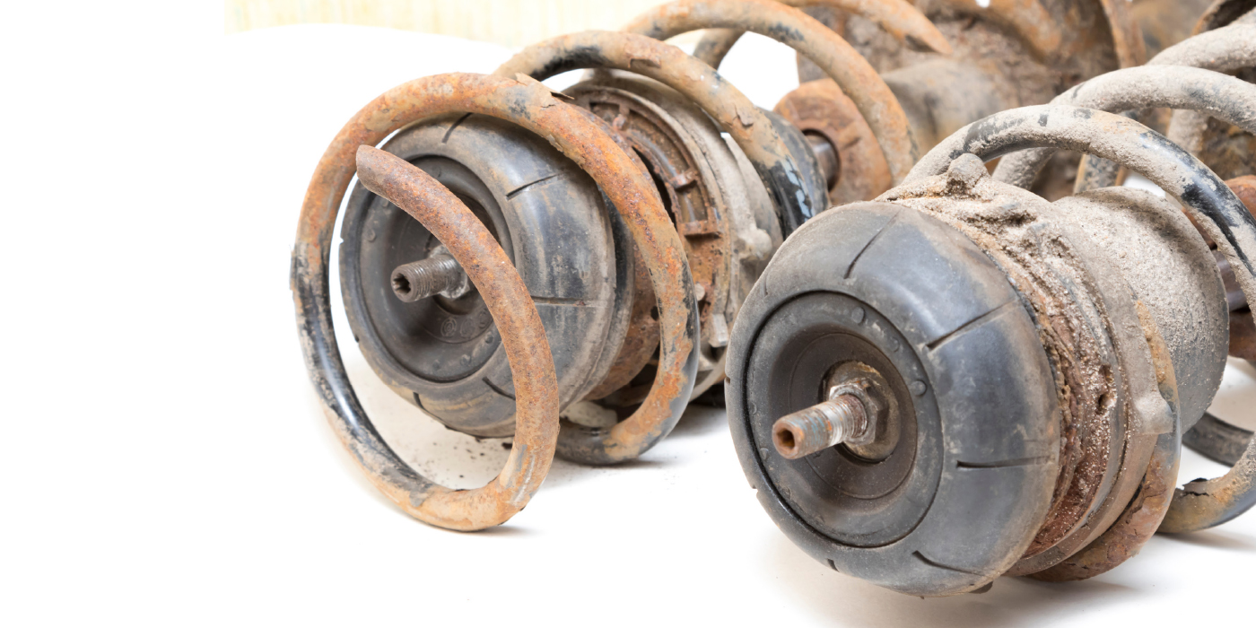
EVs are not immune to potholes, curbs and rough roads. Just like every internal combustion vehicle on the roads, the shocks, struts and springs will eventually degrade to the point where they can no longer control the movement of the suspension.
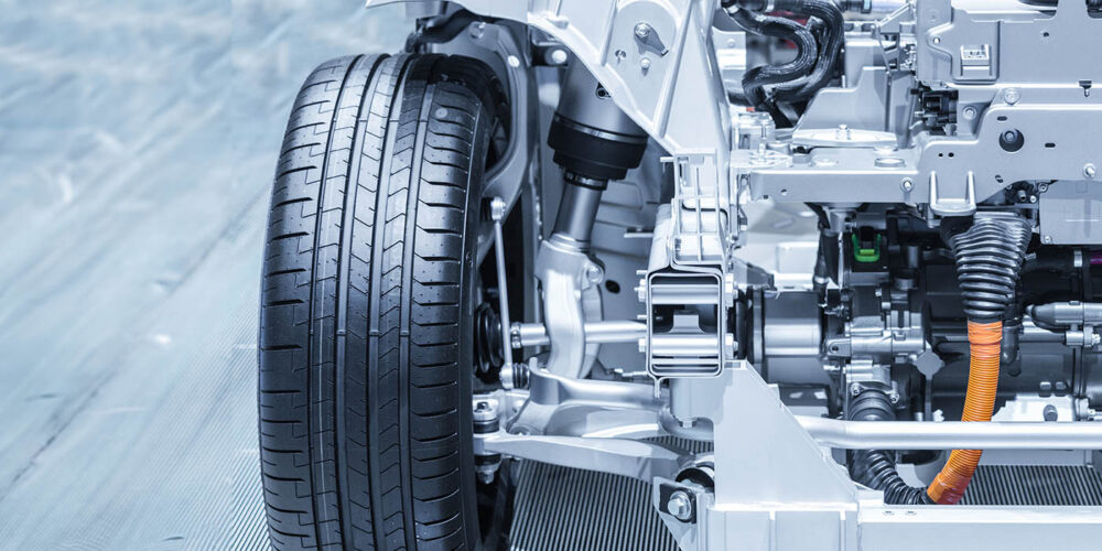
Most EVs have a weight problem that works to your advantage. The weight of the battery and motor can make some EVs 1,000-3,000 pounds heavier than their internal combustion counterparts. This will cause extra stress on the suspension.