Models affected: Cayenne/Cayenne S/Cayenne Turbo, as of model year 2003
A rattling noise may occur in the vicinity of the steering shaft and the driver’s footwell when driving any of the above models over an uneven road surface (e.g. cobblestones) within the speed range of between 18 and 24 mph (30 and 40 km/h). This is the result of play between the steering shaft and the steering shaft bearing on the upper universal joint.
On vehicles with complaints of this type, the steering shaft bearing on the upper universal joint must be preloaded to compensate for the play. 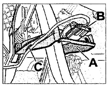
Service Procedure:
1. Raise the vehicle on a hoist until the front wheels are completely off the ground.
2. Remove the cover in the driver’s footwell under the instrument panel.
3. Release and pull off the plug on the brake light switch (Fig. 1, Item B), unclip the cable holder (Fig. 1, Item C), and remove the brake light switch holder (Fig. 1, Item A). Note: The brake light switch doesn’t need to be removed.
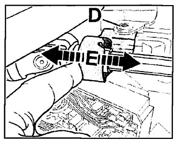 4. Unscrew the steering shaft fastening screw (Fig. 2, Item D), and completely unscrew the nut and replace it with a new fastening nut (P/N N 023 003 8). The screw does not need to be removed.
5. Tighten the screw connection until only the bearing housing can still be moved in the direction of the arrow (Fig. 2, Item E) with slight resistance.
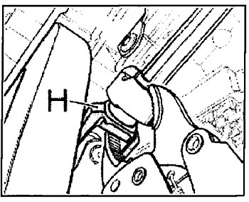 6. In order to use the vise-grip wrench on the upper universal joint in the following step, the steering shaft must be turned until the upper fork of the universal joint is in a horizontal position (Fig. 3, Item H).
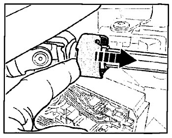 7. As shown in Fig. 4, use your finger to push — carefully and with minimum force — the bearing housing in the direction of the steering wheel (Fig. 4, arrow) as far as it will go. The steering shaft must not move while doing this. The starting position for the following steps has now been established.
8. Preload the steering shaft bearing to compensate for the play. Close the vise-grip wrench at the handle. Pre-adjust the span of the wrench jaws to approx. 50 mm using the adjustment screw on the end of the wrench’s handle.
Caution: There is danger of damaging the bearing on the upper universal joint by preloading it with excessive force. The vise-grip wrench must be closed at the handle before applying it to the universal joint and the bearing. Use the adjustment screw on the end of the vise-grip wrench’s handle to open the jaws until the wrench can be applied to the universal joint and the bearing. Note: Preload the bearing only via the adjustment screw on the vise-grip wrench.
9. Apply the vise-grip wrench to the universal joint and the upper edge of the bearing housing as shown in Fig. 5, Item F. 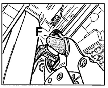 When applying the wrench to the steering shaft bearing, ensure that the wrench is not seated on the collar of the steering shaft. Use the adjustment screw to close the vise-grip wrench until the jaws fit perfectly and have no play, without altering the position of the bearing.
10. Keep turning the vise-grip wrench’s adjustment screw to close the jaws until the steering shaft bearing has moved approx. 0.5 mm in the direction of the universal joint. The measurement of approx. 0.5 mm is sufficient to compensate for the play between the steering shaft bearing and the steering shaft.
11. Hold the wrench in this position and tighten the fastening screw on the steering shaft (Fig. 6, Item G). Tightening torque: 20 Nm (14.8 ft.-lb.) 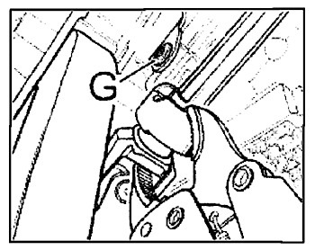
12. Open the vise-grip wrench and remove it.
13. Check the steering shaft bearing for noises by turning the steering wheel over the maximum angle without steering assistance (engine off).
14. If grinding noises occur or the bearing is intermittently catching or is running roughly, the bearing has been preloaded too tightly. In this case, all steps must be carried out again.
15. Continue with the Reassembly Procedures if the following conditions are met:
a. no noises are heard;
b. the bearing is neither catching or running roughly; and
c. the bearing is sufficiently pre-loaded.
Reassembly Procedures:
1. Install the brake light switch holder and push the electrical plug connector for the brake light switch into the switch until it snaps into place. Clip the electrical wire back to the brake light switch holder.
2. Check the operation of the brake light switch.
3. Install the cover in the driver’s footwell under the instrument panel.
4. Lower and remove vehicle from the lift.
Courtesy of ALLDATA LLC.