The cam bolt and nut kit that was used for adjusting caster and camber on all torsion bar and coil spring front suspensions prior to 2004 has been discontinued.
Now, if the caster and camber settings need to be adjusted, a washer must be installed. The right-hand upper control arm design changed from a two-piece design to a single-piece design during the 2003 model year.
The single-piece design is now the only version of the upper control arm available for service of prior model year Rangers.
Models: 1998-2001 Explorer, 1998-2003 Ranger, 2000-’03 Explorer Sport and 2001-’03 Explorer Sport Trac
Use the following Camber and Caster Adjustment procedure when either camber or caster needs to be adjusted on any suspension, or if only a caster split adjustment is needed on a vehicle equipped with a single-piece upper control arm.
Use the following Caster Split Adjustment – Two-Piece Right-Hand Upper Control Arm procedure if only a caster split adjustment is needed on a vehicle equipped with a two-piece upper control arm.
Service Procedure
Camber and Caster Adjustment
Note: The upper control arm-to-frame mounting bolts have set shims that must be replaced with washers to allow for adjustment of the arm in the frame slot. The vehicle should be supported by the lower control arm to ease movement of the upper arm in the slot.
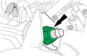
1. Remove and discard the upper control arm-to-frame nuts and shims (see Figure 1).
2. Install the new washers (W705040-5900) and nuts (N805480-5427). Tighten the nuts so there is tension, but the upper control arm can be moved for the alignment adjustment.
3. To adjust caster and camber refer to the chart. Adjustments that require moving the front and rear of the upper control arm should be made equally.
4. Torque the upper control arm-to-frame nuts to 98 lb.-ft. (133 Nm).
5. Check and, if necessary, adjust the front toe.
Caster Split Adjustment – Two-Piece Right-Hand Upper Control Arm
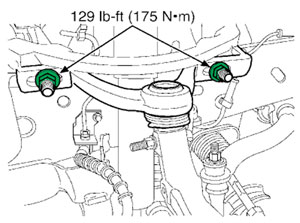
1. To decrease the right-hand caster, loosen the ball joint adjustment nuts (see Figure 2) and move the ball joint forward.
2. To increase the right-hand caster, loosen the ball joint adjustment nuts and move the ball joint rearward. 3. Torque the ball joint adjustment nuts to 129 lb.-ft. (175 Nm). 4. Check and, if necessary, adjust the front toe.
Courtesy of Mitchell 1.
For more information on Mitchell 1 products and services, automotive professionals can visit the company’s website at www.mitchell1.com.