s or abuse will develop flex points that might result in metal fatigue, cracking and eventual separation. For similar reasons, steering linkage, especially the threaded portion, should never be straightened, welded or otherwise repaired. If steering linkage parts are defective in any way, they should be replaced.
Worn ball-joint tie rod ends create another safety liability issue for shops. If the joint is worn to the point it won’t maintain an accurate toe-in angle, it should be replaced. If the joint is worn beyond existing factory specifications, it should also be replaced. In addition, it’s imperative to replace any joint that’s been repaired with epoxy injection kits or hardware that purportedly compensates for excessive wear. Any such repair might conceal wear that could cause a catastrophic separation of the joint.
RACK AND PINION STEERING LINKAGE
Most modern imports are equipped with rack and pinion steering gears that simplify the steering linkage by making the steering gear an integral part of the steering linkage. When removing tie rods for steering gear or suspension service, using the correct tool and procedure will go a long way to prevent damaging the tie rod end or steering knuckle. See Photo 1.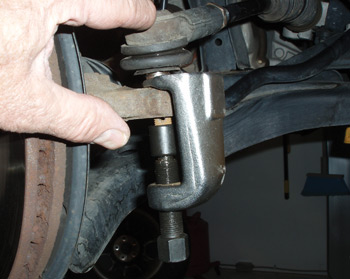
In Photo 1, the pivoting sleeve on the tool prevents damaging the threaded portion of the tie rod end. While conventional “pickle forks” are the most commonly used tool, they inevitably ruin the rubber boot that protects the tie rod end joint from dirt and water. An alternate method of removing a tie rod end without damaging the boot is to use a long pry bar to apply pressure on the tie rod end while sharply rapping the steering knuckle with a hammer. 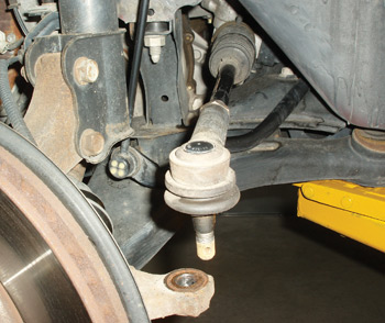
In Photo 2, the tie rod assembly is held in suspension by the preload on the inner tie rod end. If the inner end lacks preload, it will cause a rattling noise to occur on tar strips or rough roads.
If the outer tie rod end is permanently lubricated, it may also be preloaded. In most cases, the stud shouldn’t easily swivel with finger pressure (see Photo 3). The conventional method of detecting wear in conventional tie rod ends is to use the dry park test, consisting of the vehicle being parked on the floor while a helper turns the steering wheel. As the steering wheel is turned from left to right, the alignment technician looks for horizontal wear in the joint. 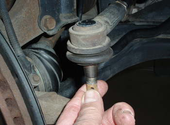
A more accurate method is to observe the change in toe angle as the wheels are pressed apart by hand on an alignment machine. This method measures the accumulated wear in the tie rod ends. Although the actual permissible amount of toe angle change is a judgmental matter for the technician, suffice it to say that if the amount of toe change exceeds the toe angle specification, the tie rod end should be replaced.
An additional caveat of the hand press method is to push the steering tires apart at the front on rear-wheel-drive vehicles to simulate rolling and braking resistance. On front-wheel-drive or all-wheel-drive vehicles, hand press the steering tires at the rear to simulate the pulling effect of front-wheel drive.
When installing a tie rod end, make sure that the tapered hole is free of rust, dirt or any solid material that will cause the stud to loosen when placed back in service (see Photo 4). It’s also important to never over-torque the castellated nut holding the stud in place.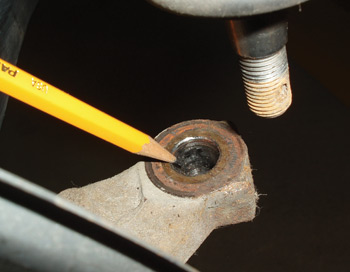
Most tie rod end retaining nuts torque in the 30- to 40-foot-pound range. Over-torquing the stud can possibly ruin the steering knuckle by enlarging the tapered hole in the knuckle’s steering arm (see Photo 5). Always lubricate the threads with a drop of non-detergent motor oil when torquing suspension components (see Photo 6).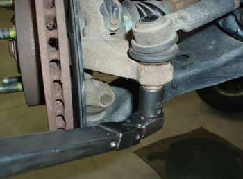
Last, lock the nut in place by installing a cotter pin of an appropriate diameter and make sure that the tie rod assembly is free to pivot at the tie rod end.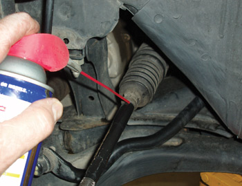
PARALLELOGRAM LINKAGES
The steering linkage of a conventional parallelogram linkage system consists of a connecting link attached to a pitman arm, mounted on the steering gear and idler arm mounted on the frame. In the straight-ahead position, the steering gear pitman arm, idler arm and connecting link form a rectangle (see Photo 7). As the steering linkage moves to the right or left, it forms a parallelogram. 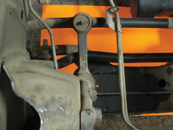
In addition, the connecting link must remain level when negotiating a turn. If the vehicle’s frame is bent or the steering gear or idler arm is mounted incorrectly, the resulting incorrect geometry will adversely affect the toe-out of the wheels when negotiating a turn. The Ackerman Effect, as it is more popularly known, allows the inside wheel to toe out about two degrees more than the outside wheel to accommodate different turning radiuses when navigating a corner.
To check idler arm wear on a parallelogram steering linkage, jack the passenger side wheel off the floor and firmly grasp the tire at the 9 and 3 o’clock positions. By pivoting the tire by hand from right to left, the toe angle variation allowed by the idler arm can be evaluated. 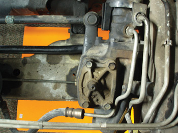
Before adjusting the sector shaft end play, always make sure that the pitman and idler arms form a perfect 90° angle (see Photo 8). At this position, the steering gear should be on “high point” or midway in its travel and ready for the end play to be removed from the sector shaft. When a parallelogram steering system is properly adjusted and installed, it should steer precisely without wander or pull.