 By Ed Sunkin
The Chrysler Sebring convertible, launched in 1996 as the sister car to the Sebring Coupe, didn’t share many components with the coupe. And, this model was also unique to Chrysler, as unlike most other Chrysler brand cars, no Dodge or Plymouth counterpart was offered.
One of the biggest differences in servicing the Sebring convertible from other Chrysler models was its battery location — behind the driver’s side wheel well.
Servicing the first-generation Sebring convertible battery caused quite a bit of complaints from DIYers who had trouble replacing this component, and it created some confusion when it came to charging a dead battery or testing for electrical draws. 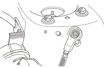
(Eventually, Chrysler changed the battery location in its convertible Sebrings to make it more accessible. But, the carmaker continued to use this wheel well location design in other Chrysler vehicle models in years following.)
Chrysler claims battery removal is possible on its first-generation convertibles without removing the driver’s side wheel — providing the vehicle is on a lift.
To remove the battery, make sure that the ignition switch is in the OFF UNLOCKED position. Next, disconnect the battery negative cable from the remote negative terminal on the shock tower (see Figure 1 and Photo 1).
Turn the steering wheel to the full left position and twist the four plastic screws one-quarter turn to release the shield.
Remove the shield and disconnect the battery blanket heater cord — if equipped.
Next, remove the battery negative cable followed by the positive cable. You’ll need to remove the bolt attaching the battery strap to the battery hold down bracket (see Figure 2).
After you remove the hold-down bracket bolt, slide the battery to the rear of the tray and lift it
over the lip. (For battery installation, reverse the preceding procedures.)
Note: A battery blanket heater is used with Alaska and Canada cold-weather packages, though we wonder how many convertibles are driven around up in Alaska. The 110-volt AC blanket, used to improve battery cold-start ability, uses an electronic voltage regulator that controls the battery charging. Only a Chrysler-approved battery/blanket heater combination should be used here. Chrysler warns the addition of an aftermarket battery heater or engine block heater will adversely affect battery charging and will result in battery discharge or damage. 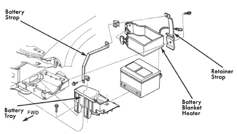
Causes of Battery Discharge
It is normal to have up to a 30milliamperes continuous electrical draw on the battery. This draw will occur with the ignition in the OFF position, and the courtesy, dome, storage compartments and engine compartments lights off. This continuous draw is due to various electronic features or accessories that require electrical current with the ignition off to function properly.
Chrysler recommends that when a vehicle is not used for 20 days or more, the Ignition Off Draw (IOD) fuse, located in the Power Distribution Center, should be disconnected.
Battery Ignition Off Draw Testing
Obviously, high battery current draw with the ignition switch in the OFF position will discharge a battery. After a dead battery is serviced, the Sebring’s vehicle IOD should be checked. To determine if a high-current draw condition exists, check the vehicle using a multimeter in the milliampere scale and the following steps.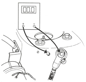
Test Procedure
1. Verify all electrical accessories are off.
• Remove the key from the ignition switch.
• Turn off all lamps.
• Ensure that the trunk compartment lamp is off when the trunk is closed and that the hood lamp in the engine compartment is off when the hood is closed.
• Make sure that glove box compartment lamp is off when the glove box door is closed.
• Check the visor vanity lamps to make sure they are off.
• Close all the vehicle doors and allow the Illuminated Entry System to time out after about 30 seconds.
2. Disconnect the battery negative remote cable. (See Figure 1.) Caution: Always disconnect the milliamp meter before opening the door.
3. Using a multimeter that has at least a milliamp range of 200mA, set the meter to its highest mA range.
Connect the meter between the battery negative remote terminal and the battery negative remote stud (Figure 3).
• If the reading is less than 30 mA, then the system is OK.
• If the reading is more than 30 mA, go to the High Milliamp Reading section.
Remember, each time the milliamp meter is disconnected and connected, all electronic timer functions will be activated for about 1 minute.
High Milliamp Reading
There is either a short circuit or a fault in an electronic module. In the Sebring design, there are seven fuses in the Power Distribution Center and Junction Block that feed the modules with ignition off draw.
Ensure that all electronic timer functions are timed out before testing any of the components.
The seven fuses include: (Power Distribution Center) the automatic transmission control module, power control module and the hazard flasher fuses, all rated 20 amps. In the Junction Block are: Canadian daytime running lamps, optional audio power amplifier and the instrument cluster fuses — all rated 20 amps — as well as the interior lamp fuse rated at 10 amps.
1. Remove all seven fuses. By removing these fuses, all ignition off draw from the vehicle electronics will be disconnected. There should be no reading on the milliamp meter. If there is no reading, go to Step 2. If there is a reading, then there is a short circuit, and you should refer to the Group 8W wiring section of the Chrysler Sebring service manual.
2. Install the daytime running lamp (DRL) fuse, if equipped. If the meter has no reading, go to step 4. If there is a reading, go to Step 3.
3. Disconnect the DRL module. If the meter has no reading, replace the DRL module. If the meter has a reading, then there is a short circuit in the L25 circuit. Refer to the Group 8W wiring diagrams of the Chrysler Sebring service manual.
4. Install the power amplifier fuse. If the meter has no reading, go to Step 6. If there is a reading, go to Step 5.
5. Disconnect the power amplifier. If the meter has no reading, replace the power amplifier. If the meter has a reading, then there is a short circuit in the L30 circuit. Refer to the Group 8W wiring diagrams of the Chrysler Sebring service manual.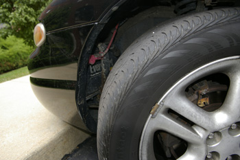
6. Install the interior lamp fuse. If the meter has no reading, go to step 7. If there is a reading, go to Step A.
A. Disconnect the radio. If the meter has no reading, replace the radio. If the meter has a reading, go to Step B.
B. Disconnect the power sunroof module by disconnecting the headliner connector. The connector is located in the back of the junction block, below the fuses. If the meter has no reading, replace the sunroof module. If the meter has a reading, go to Step C.
C. Disconnect the body control module. If the meter has no reading, replace body control module. If the test lamp does not go out, then there is a short circuit in the M1 circuit. Refer to the Group 8W wiring diagrams of the Chrysler Sebring service manual.
7. Install the automatic transmission control module fuse. If the meter has no reading, go to step 9. If there is a reading, go to Step 8.
8. Disconnect the automatic transmission control module. If the meter has no reading, replace the automatic transmission control module. If the meter has a reading, then there is a short circuit in the A14 circuit. Refer to the Group 8W wiring diagrams of the Chrysler Sebring service manual.
9. Install the power control module fuse. If the meter has no reading, go to step 11. If there is a reading, go to Step 10.
10. Disconnect the power control module. If the meter has no reading, replace Power control module. If the meter has a reading, then there is a short circuit in the A14 circuit. Refer to the Group 8W wiring diagrams of the Chrysler Sebring service manual.
11. Install the instrument cluster fuse. If the meter has no reading, go to step 13. If there is a reading, go to 12.
12. Disconnect the instrument cluster. If the meter has no reading, replace the instrument cluster. If the meter has a reading, then there is a short circuit in the F33 circuit. Refer to the Group 8W wiring diagrams of the Chrysler Sebring service manual.
13. Install the hazard flasher. If the meter has no reading, there is no ignition off draw. If there is a reading, go to Step 14.
14. Disconnect the hazard flasher. If the meter has no reading, replace the hazard flasher. If the meter has a reading, then there is a short circuit in the A15 circuit. Refer to the Group 8W wiring diagrams of the Chrysler Sebring service manual.
Source: Chrysler LLC