As the metal tooth passed by the permanent magnet wrapped in copper wire, the magnetic field was altered and measured by a computer. This is not a sci-fi novel, but how a passive wheel speed sensor works.
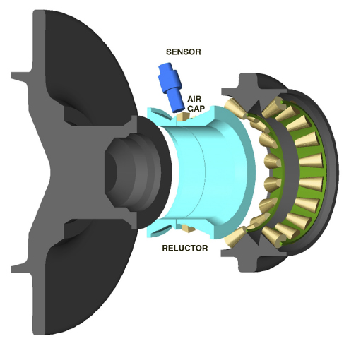
A passive wheel speed sensor is often called a “variable reluctance sensor” by some engineers. The sensor is mounted at a specific gap from a toothed reluctor ring. As the teeth pass by the wheel speed sensor, it changes the magnetic field and produces alternating current or AC voltage. The AC voltage can be seen by a scope as a sine wave.
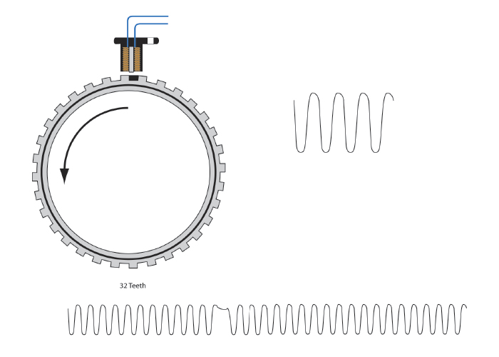
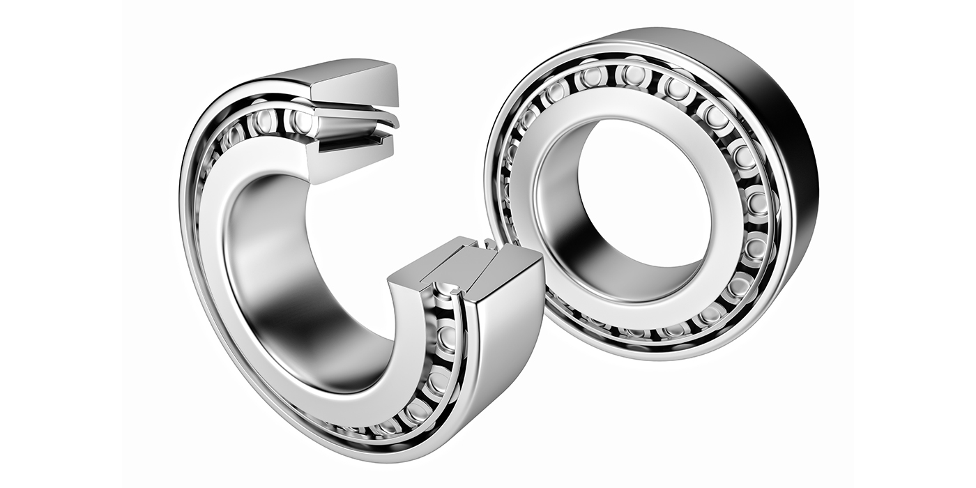
The voltage signal will increase in amplitude with an increase in the speed of the reluctor ring. The change in amplitude can affect the switching toggle to the computer, where a cracked reluctor ring may produce an extra switching toggle. The variable-reluctance sensor is a two-wire sensor in a hub unit between the bearing races.
Passive sensors are less accurate and might read 3-5 mph on a scan tool when the vehicle is sitting still. Passive sensors are still used on the rear of some vehicles and the front wheels will have more accurate active sensors that can detect wheel movement at much lower speeds.
Testing
With the meter set to AC voltage, spin the wheel by hand. The sensor should produce between 0.5 to 1 volt of AC current. The faster the wheel is turned, the more voltage is produced. A scope can be used to observe the waveform. Changes to the sine wave can indicate problems with the reluctor ring or sensor.
If the signal is viewed on a scope, the voltage will rise above the ground or zero line. On this vehicle, there is a 2.5-volt bias. To measure this, have the ground lead on the battery ground, and the positive lead connected to the signal wire. Without the wheel spinning, you can observe the DC voltage being supplied to the circuit.
Bias Voltage Self Diagnostics
When a vehicle is first started and the ABS module wakes up, it sends DC voltage to the wheel speed sensors for a split second. The ABS module is looking at the voltage coming back from the sensor. High resistance or an open circuit can immediately be detected because the voltage coming back to the module will be too low or not at all. Often, with these systems the trouble is not the sensor, but the bias voltage as it goes through the harness and connectors.
With the sensor disconnected, connect the positive lead to the signal wire and the negative lead to the other side that is the ground for the ABS module. This voltage comes directly from the ABS module and will be between 1.5 and 5 volts. This is the bias voltage from the ABS module. Any voltage outside of the manufacturer’s specification may indicate a problem with the harness.
Unwanted ABS Activation In Passive Sensors
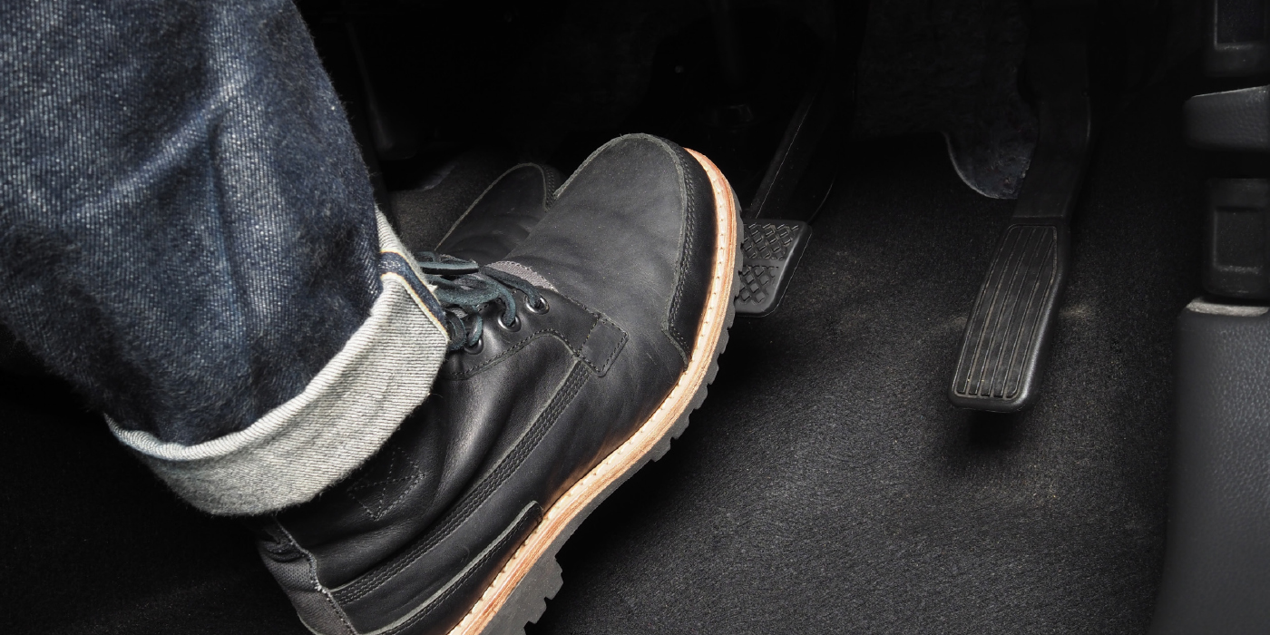
You may have a driver complain that the ABS system activates during conditions when it should not, like coming to a stop below 10 mph. The most likely suspects are the wheel speed sensor and the reluctor ring.
Metal debris can build up on the tip of the wheel speed sensor. This changes the signal and reduces the amount of AC voltage the magnet and coils generate. Damage to the coils surrounding the magnet can also alter the signal. The metallic debris can alter the signal and make the ABS module think one wheel is stopped compared the other wheels.
Damage to the reluctor ring changes the air gap. The most common issue is corrosion between ring and the rotating component. As the corrosion gets under the reluctor ring, it changes the air gap and signal coming from the wheel speed sensor.