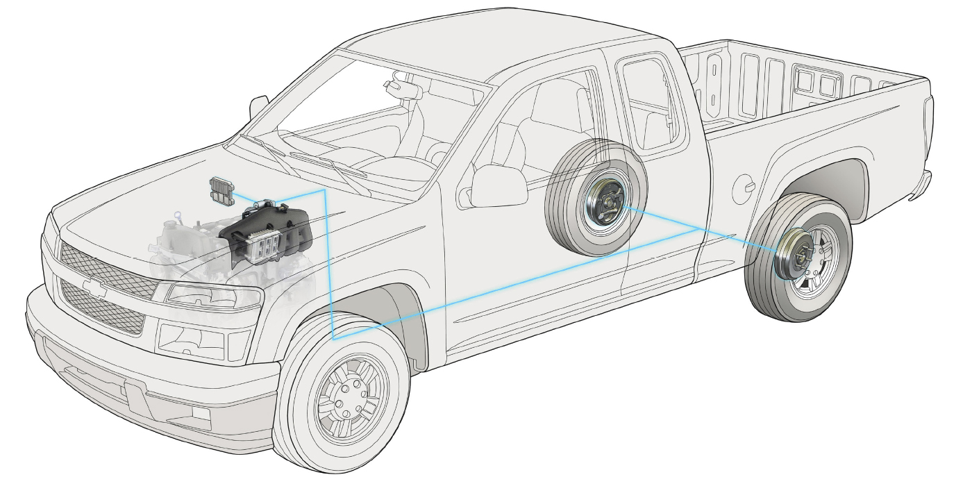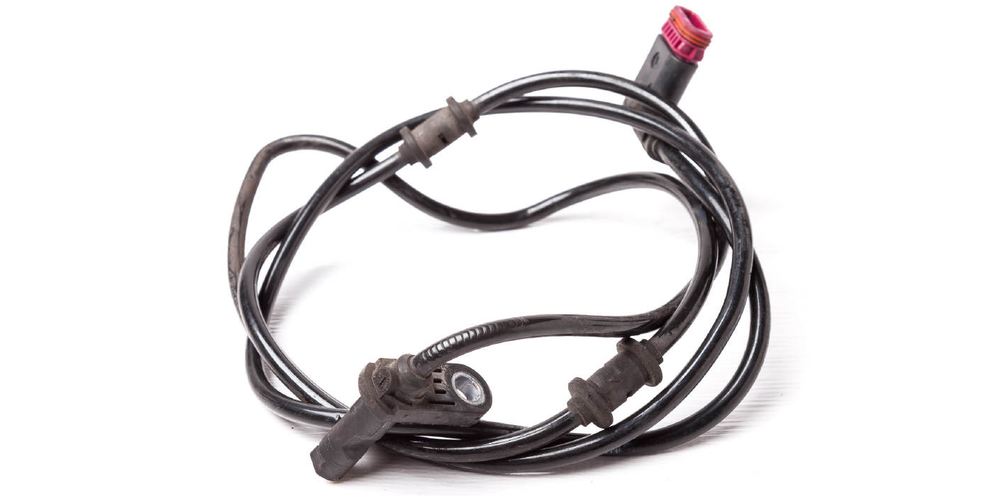
There are two “types” of sensors generally found on the modern car — the passive speed sensor and the active speed sensor. They both perform the same function, but work entirely different.
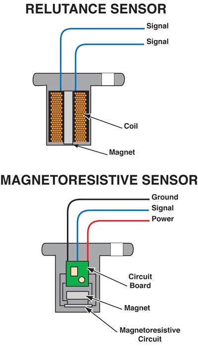
The passive speed sensor uses a magnet with fine copper wire wrapped around it to create its own alternating magnetic field. The polarity changes from positive to negative as the tone ring passes by the magnetic field. This frequency changes with wheel speed.
The newer active sensor uses a digital signal created by the ABS controller. This type of sensor uses a Hall effect or a variable reluctance signal with a square wave pattern. The sensor consists of two wires; one is used as the positive (DC) voltage from the controller and the other lead as the return (ground) to it. The advantages of the active speed sensors are their ability to read more accurately at slow speeds than the passive speed sensors. They don’t have to self-generate the needed voltage by the spinning action of the wheel. Also, since these sensors use a DC voltage, they can detect not only the speed of the wheel, but also the direction of travel. This allows the controller the ability to calculate not only wheel speed, but it can also be used for the hill holding and hill descent control features found on some vehicles.
How It Works
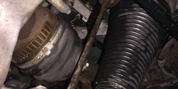
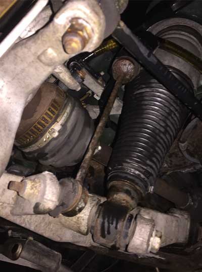
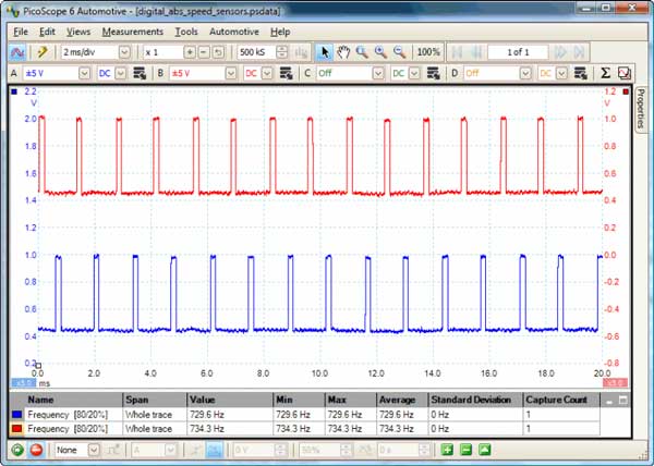
The active speed sensor or “Magneto Resistive Sensor” consists of two parallel resistors and a magnetic material located at a precise distance from a permanent magnet. The resistors are about 1.4k ohms each, however if you were to measure the resistance at the wire ends you would probably see 5 to 6 mega ohms. (That’s because you are reading the resistance values of not only the resistors but the magnetic material inside the sensor, as well.) These parallel resistors work together to create the voltage changes you’ll see on your lab scope as the tone wheel passes by the internal magnet. The tone wheel (if flattened out) looks like the square wave pattern it creates. As the high part of the tone wheel’s tooth is near the sensor, a higher voltage is created, while the opposite is true when the lower part of the tone wheel is near the sensor.
 Even though it is close to battery voltage at the sensor (10.6v is what I’ve found) you won’t be able to use a test light to read it. A test light consists of a ground lead, a bulb (resistance) and the positive end, which is basically the same thing the sensor has internally, minus the magnets. If you try stabbing a test light on the positive lead to the sensor, the computer sees that as a possible short to ground. Meaning, it thinks your test light is the sensor because the return voltage on the groundside of the sensor has drastically changed. In fact, in most of these ABS systems, if you do “short” the lead, the processor shuts that sensor off (0.0v) until the next key cycle. This way, it avoids any harm coming to the internal circuits of the processor. But, if you continued to check the circuit without turning off the key, you’d end up back at the processor and more than likely come to the conclusion the processor is bad. It’s not … just cycle the key and recheck it.
Testing an Active Speed Sensor
The best tool for testing the active speed sensor is a good scanner, preferably one that can show the separate speed sensors in graph form. A lab scope is probably the best for a more precise answer and can be attached directly at the sensor to read the individual sensors or wires, rather than the entire system as with the scanner. But, if you’re looking for a quick test to determine if just the speed sensor is in working order, you can make a quick little tester yourself.
LED Tester
You’ll need a 220-ohm resistor, an LED and a 12v battery source. Disconnect the sensor from the car (Caution: Do not try this with it being hooked up!), and hook up the battery to one side of the sensor leads.
The other lead from the sensor is hooked up to your resistor and LED, while the remaining lead from your LED should return to the battery. An LED is polarity-conscious, so be sure to have the current flowing in the right direction or it won’t light up at all. (The sensor doesn’t care which direction, only the LED does). What you’ll see as you spin the wheel is your LED blinking on and off with an increasing and decreasing blink rate as the wheel speed changes.
This is one of those times when the old school test light isn’t going to help you out at all; in fact, it might create more of a problem. Your scope or your scanner on these types of sensors is the better choice. However, this quick little LED tester might help you with your diagnostics. It won’t test the entire system, but it will confirm if the speed sensor is functioning. Testing is always better when you have more than one method to determine the condition of a component. In this case, a scanner, a scope or a homemade LED tester can help you in diagnosing these active speed sensors.
Always test first, test second … and when still in doubt … test a third time.