By Eric Seifert
Automotive Technical Editor
Bill’s 2004 Chevy Silverado made an odd clunking noise on the freeway when he ran over those little reflectors while changing lanes. He could hear and feel the “clunk” in the steering wheel.
Some customers may comment on a clunk-type noise coming from under the hood that also can be felt in the steering wheel. These conditions may be more noticeable when turning at low speeds on rough surfaces.
Use the information below to help diagnose the source of the noise.
Intermediate Shaft Clunk – Intermediate shaft clunk is heard and FELT in the steering wheel and/or steering column area, typically while driving on rough road surfaces with steering wheel input. To eliminate the clunk, replace the steering column upper intermediate shaft with an improved design (GM P/N 19153614) using the procedure below.
Do NOT lubricate or exercise the I-Shaft. I-Shaft P/N 19153614 has been designed to replace previous designed dampened and non-dampened I-Shafts. The physical difference in the yoke size will accommodate all vehicles listed in this procedure. Due to the design of the new I-Shaft, it is not possible to lubricate/grease the I-Shaft. The new intermediate shaft along with GM tool J 42640 – Steering Column Anti-Rotation Pin (for newer models) will be required to complete the procedure.
Applicable Vehicles:
2002-2006 Cadillac Escalade Models
1999-2007 Chevrolet Silverado Models (Classic)
2000-2006 Chevrolet Suburban, Tahoe Models
2002-2006 Chevrolet Avalanche
1999-2007 GMC Sierra Models (Classic)
2000-2006 GMC Yukon, Yukon XL Models
2003-2006 HUMMER H2
Attention: This Procedure DOES NOT include Mid-Size Utilities such as Buick Rainier, Chevrolet TrailBlazer, GMC Envoy or Oldsmobile Bravada models.
Repair Procedure:
Review safety procedures in ALLDATA Repair before beginning.
 1. Set the front wheels in the straight-ahead position.
On the 2002 and later model-year vehicles, the steering column LOCK was removed from the steering column. It is critical that the J 42640 – Steering Column Anti-Rotation Pin is used when servicing steering columns on 2002 and later vehicles. Failure to use the J 42640 may result in damage to the SIR coil.
2. Set the steering wheel in the LOCK position on 2001 and prior model year vehicles.
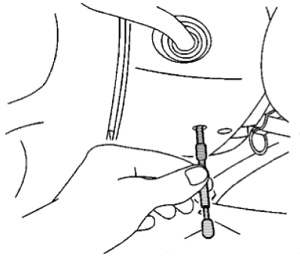
For 2002 and newer vehicles, install the J 42640 in the
steering column lower access hole.
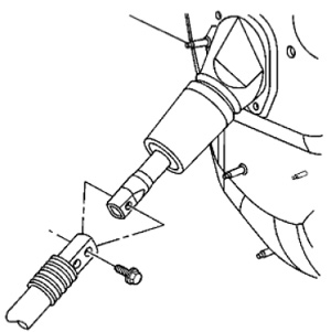
3. From under the hood, remove the lower bolt that connects the upper intermediate shaft to the steering gear coupling shaft. Slide the shaft towards the dash in order to disengage the shaft from the steering gear coupling shaft.
4. For vehicles equipped with adjustable foot pedals, perform the
following steps:
a) Reposition the carpet away from the accelerator pedal position (APP) sensor.
b) Remove the two nuts retaining the accelerator pedal to the bulkhead.
c) Reposition the accelerator pedal out of the way so the intermediate shaft can be removed.
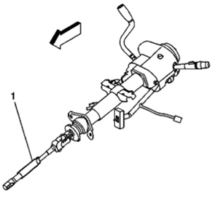
 5. From inside the vehicle, remove the upper bolt from the upper intermediate steering shaft (1) to the steering column connection. Remove the upper intermediate steering shaft assembly.
6. From inside the vehicle, slide the shaft down and off the steering column.
7. From inside the vehicle, slide the upper intermediate shaft through the dash boot seal and remove the shaft from the vehicle.
8. Replace the upper intermediate shaft.
9. Install the upper intermediate steering shaft through the dash boot seal and slide the lower end into the steering gear coupling shaft.
 10. Raise the upper end of the intermediate steering shaft and install into the steering column shaft.
11. Install the upper bolt and nut. Tighten the bolt to 47 N.m (35 lb ft).
12. Install the lower bolt and nut. Tighten the bolt to 50 N.m (37 lb ft).
13. For vehicles equipped with adjustable foot pedals, perform the following steps:
a) Reposition the accelerator pedals into position on the bulkhead.
b) Install the two retaining nuts. Tighten the nuts to 20 N.m (15 lb ft).
14. Reposition the carpet into place.
Written by ALLDATA Technical Editor, Eric Seifert. Eric is an ASE certified Master Technician and Engine Machinist. He is a graduate of the De Anza College Automotive Technology Program, with 20 years of independent shop and parts store experience.
For additional information, visit www.alldata.com.