By Eric Seifert
ALLDATA Automotive Technical Editor
When Jeff called to discuss the lack of power in his 2002 Toyota Prius, I have to admit I was a little confused. The Prius was designed to be economical, not to compete in the stoplight grand prix. He said it felt sluggish, and recently some lights in the instrument panel had come on. Jeff was lucky; Toyota had already identified the problem and it is covered by the 96-month/100,000-mile Toyota Hybrid Vehicle System Component Warranty. I suggested he contact the local dealer.
Some 2001-’03 model-year Prius vehicles may exhibit a Master, Hybrid and MIL warning light on with DTC P3130, and possibly P3125 with sub code 264. When the vehicle is parked after prolonged operation in heavy stop-and-go traffic, or sustained high speeds in ambient temperatures above 90° F (32° C), and when attempting to restart, the vehicle may experience an abnormally low power output condition or inability to “Ready On.”
If the vehicle is out of warranty, the following parts and tools will be required to perform the repair:
- 1 Toyota P/N G9200-47071 Inverter Assembly, with Converter;
- 1 Toyota P/N 00272-1LLAC Long Life Coolant (or equivalent);
- Toyota P/N 01001271 Diagnostic Tester kit and Program Card with version 10.2a software and later (or equivalents); and
- A pair of Electrical Insulating Gloves, Toyota P/N 00002-03100-S (small), 00002-03200-M (medium) or 00002-03300-L (large).
Repair Procedure
Verify proper operation of the following systems:
• Check the coolant level in the inverter reservoir tank. If the fluid level is low, examine cooling system components and isolate the source for leaks.
• Verify the inverter coolant pump is operating properly.
• Check for the presence of air bubbles in the cooling system.
• Check for coolant or air flow obstructions to the inverter heat exchanger and proper radiator side seal condition.
If no problems are found with these components, proceed with the inverter replacement.
Caution: A repair operation incorrectly performed on the hybrid vehicle could cause an electrical shock, leakage or explosion. Be sure to perform repair operations correctly.
• Remove the key from the ignition switch.
• Ensure that the charge connector is disconnected.
• Always wear insulating gloves.
• Disconnect the negative (-) terminal cable from auxiliary battery.
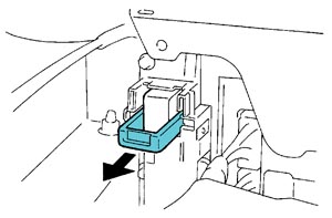 1. Remove the service plug and do not start any repair operation before five minutes have passed. See Figure 1.
Caution: Due to the discharge resistance, it takes at least five minutes before the 273.6V circuit is sufficiently discharged from the condenser in the inverter circuit. Even after the five minutes have passed, the following precaution should be observed:
• Before touching a 273.6V cable or any other cable that you cannot identify, use the tester to confirm that the voltage through the cable is 12V or less.
• After removing the service plug, cover the plug connector using rubber or vinyl electrical insulation tape.
2. After removing the 273.6V cable, be sure to cover each terminal using vinyl electrical insulation tape.
3. Do not leave tools or parts (bolts, nuts, etc.) inside the cabin.
4. Do not wear metallic objects such as mechanical pencils or scales.
Caution: A metallic object may drop and cause a short-circuit.
5. Drain the coolant.
6. Remove and replace the inverter assembly with converter.
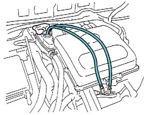 7. Bleed the coolant system of air. See Figure 2.
A. Loosen the bleeder plug. Attach 0.12-0.16 in. (3-4 mm) internal diameter clear vacuum tubing between the bleeder fitting and the coolant reservoir.
Note: Use Toyota Long Life Coolant (or equivalent) mixed 50/50 with distilled water.
• To prevent coolant from splashing, place a shop rag on the overflow pipe.
B. Fill the reservoir until the coolant level in the hose connected to the bleeder plugs reaches the same level as the FULL mark on the reservoir tank.
C. Tighten the two bleeder plugs.
D. Activate the water pump by turning the ignition switch to the on position. Allow the pump to operate for 20 seconds, then turn the ignition switch to the off position.
E. Loosen the two bleeder plugs to bleed the air.
F. Close the two bleeder plugs again.
G. Repeat steps E and F until the operation sound of the pump decreases and the coolant in the reservoir tank moves faster.
H. With the ignition switch on, wait for approximately five minutes.
I. Adjust the coolant level inside the reservoir tank.
8. After replacing the inverter assembly with converter, clear the DTC. Even if the master warning light is not lit, clear the DTC using a Toyota Diagnostic Tester (or equivalent).
• If a Toyota Diagnostic Tester cannot be used, disconnect the auxiliary battery for one minute or more and connect it again.
9. Verification of the inverter assembly with converter after replacement: Depressing the accelerator pedal to a degree of 50%, increase the speed up to approximately 9 mph three or four times to check that there is no problem in the inverter operation.
10. Test drive the vehicle to ensure that all repairs are satisfactory.
Eric Seifert is an ASE certified Master Technician and Engine Machinist, with 20 years of independent shop and parts store experience.
Courtesy of ALLDATA.
For additional information, visit www.alldata.com.