This bulletin provides information on a change to Sportage 4WD hub seals. To improve hub vacuum sealing during 4WD operation, a new inner seal along with corresponding revisions to knuckles and CV shafts has been developed. This new seal design was incorporated from Oct. 21, 2000 production.
To service earlier 1998-2001 vehicles (prior to Oct. 21, 2000 production) that experience inner seal problems, a service kit is available to retrofit the new seal (P/N QK081 33 020DQ w/o ABS, P/N QK082 33 020 EQ w/ABS). Use the procedures in this bulletin to install the service kit.
Affected Vehicles: 1998, 1999, 2000 and some 2001 Sportage 4WD models with production dates between Sept. 1, 1997, and Oct. 21, 2000.
Repair Procedure:
- Raise the vehicle on a hoist.
- Remove the front wheel/tire assembly.
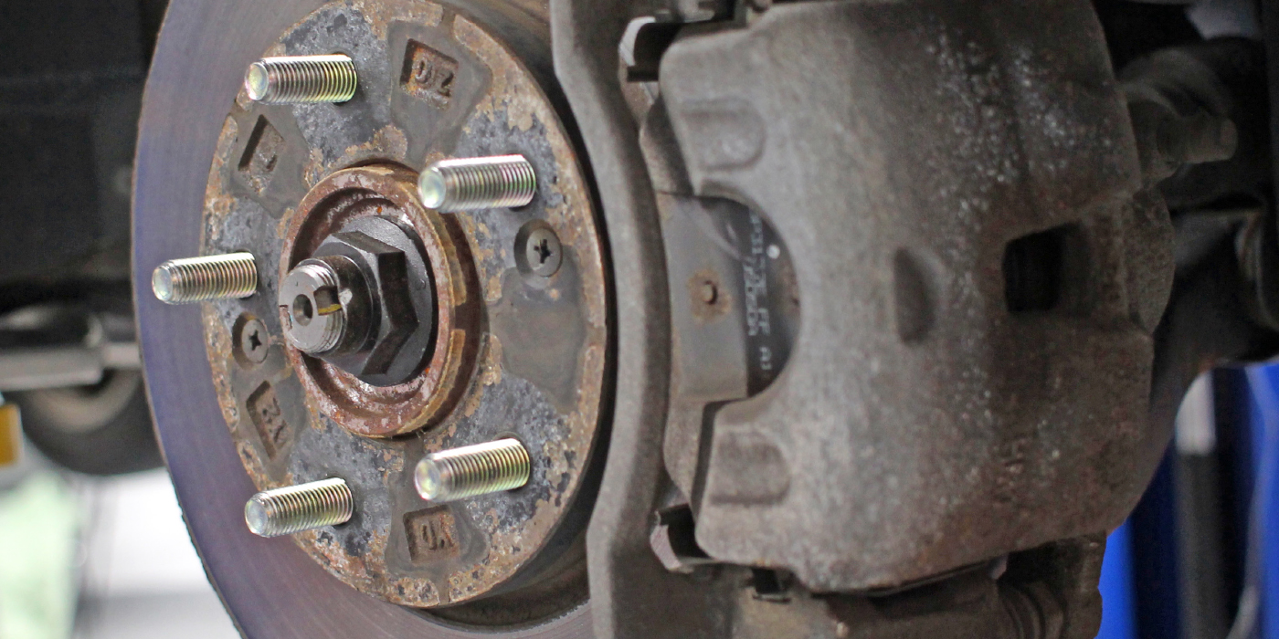
- Remove the two bolts attaching the brake caliper/anchor to the knuckle and remove the caliper/anchor assembly from the rotor. Secure the caliper/anchor assembly out of the way with wire or tie wraps. Note: Do not allow the caliper/anchor assembly to hang from the brake hose.
- Remove the two screws securing the brake rotor to the wheel hub and remove the rotor.
- Disconnect the vacuum hose from the fitting on the knuckle.
- Remove the ABS sensor attaching bolt and sensor from the knuckle (if ABS equipped).
- Remove the six bolts securing the vacuum locking hub to the wheel hub and remove the hub.
- Remove the snap ring and washer from the CV axle shaft. Discard the snap ring.
- Remove the tie rod cotter pin and nut, then with a suitable puller (such as Snap-on 0J82B), disconnect the tie rod end from the knuckle. Note: Do not use a pickle fork-type tie-rod separator; seal damage will occur.
- Remove the lower ball joint cotter pin and nut, then, with a suitable puller (such as Snap-on CJ119B), separate the ball joint from the knuckle. Note: Do not use a pickle fork-type ball joint separator; seal damage will occur.
- Remove the 10 mm pinch bolt and nut securing upper ball joint to the knuckle.
- Remove the knuckle/hub assembly from the vehicle.
- Using a suitable jack under the lower control arm, load the suspension and raise the strut fork opening sufficiently to allow for driveshaft removal. Pull the CV shaft free from the front axle by using the outer part of shaft as a slide hammer.
- Remove the shaft from the vehicle, carefully guiding the CV joint through the strut fork. Note: Apply lubricant to the CV boot edge and fork edges to facilitate removal. Do not use undue force as damage to the boot may occur.
- Mark the edge of the lower control arm at 1/8-inch from the edge.
- Remove the 1/8-inch of material marked in step 15 by grinding the edge at an angle. Touch up the reworked area with black paint. Note: This material removal on the lower control arm is necessary to prevent interference between the lower control arm and the new knuckle and/or inner seal dust shield on the CV shaft.
- Inspect the retaining ring on the output shaft of the front axle; replace if damaged. Position/rotate the new driveshaft to line up with the splines in the front axle output shaft, then install it by pushing it into place using the outer part of the shaft as a slide hammer.
- Unload the suspension and remove the jack.
- 19. Remove the four bolts and separate the old ball joint from the lower control arm. Install the ball joint on the new knuckle and hand-tighten the attaching nut. Note: Installing the knuckle to the upper control arm first with the lower ball joint already installed on the knuckle will help prevent damage to the dust shield on the driveshaft and/or seal.
- Apply grease to the inner bearing surface and to both sides of the new knuckle spacer and install it onto the CV joint.Note: The spacer has a chamfer on the inside diameter. This chamfer must face the CV joint.
- Apply grease to the inner seal in the new knuckle/hub assembly.
- Install the knuckle/hub assembly by first installing it over the CV axle shaft, then insert the upper ball joint through the top of knuckle. Retain with a 10 mm pinch bolt and nut. Note: Suspending the knuckle from the upper control arm before attaching the ball joint to the lower control arm will help prevent damage to the dust shield on the driveshaft and/or to the seal.
- Make sure the CV axle shaft is inserted all the way into the hub, install the washer and secure it with a new snap ring.
- Lift the knuckle assembly up and guide the lower ball joint flange under the lower control arm and secure it with four bolts. Torque the bolts to 16-19 lb.-ft.
- Tighten the upper ball joint pinch bolt to 36 lb.-ft.
- Tighten the lower ball joint nut to 110 lb.-ft. and install a new cotter pin.
- Insert the tie rod end into the knuckle, install a nut, tighten to 27 lb.-ft., and install a new cotter pin.
- Make sure there is no interference between the lower control arm and knuckle or the inner seal dust shield when turning the steering wheel from full left to full right. If there is interference, recheck/repeat steps 15 and 16.
- Install the ABS sensor into the knuckle and tighten the mounting bolt to 7 lb.-ft. (if ABS equipped).
- Apply a small amount of oil to the O-ring on the vacuum locking hub.
- Install the vacuum locking hub to the wheel hub and tighten the six bolts in two passes using a crisscross pattern.
- A. First pass: Tighten to 19 lb.-ft.
- B. Second pass: Tighten to 23 lb.-ft.
- Connect a hand-held vacuum pump to the vacuum fitting on the knuckle and check for vacuum leakage. The hub should hold a vacuum of 20 in. Hg for 10-20 seconds. If it doesn’t, check for seal damage or misinstallation and excessive wheel bearing play.
- Check the vacuum hoses, steel lines, vacuum canister and vacuum solenoid for restrictions, cracks, and contamination or rust. Clear with compressed air if any debris or restrictions are found. Replace any unserviceable parts.
- Connect the vacuum hose to the fitting on the knuckle.
- Install the brake rotor and two retaining screws.
- Install the brake caliper/anchor assembly and tighten the two mounting bolts to 72 lb.-ft.
- Install the wheel/tire assembly and tighten the lug nuts to 74 lb.-ft.
- Repeat the procedure for the other side of the vehicle.
- Confirm that the vacuum solenoid harness connector is securely installed on the solenoid. Note: This connector may have been disconnected on vehicles modified for use with earlier-style locking hubs.
- Test-drive the vehicle and verify 4WD operation.
Technical service bulletin courtesy of IDENTIFIX.
For additional tech tips, visit www.identifix.com.