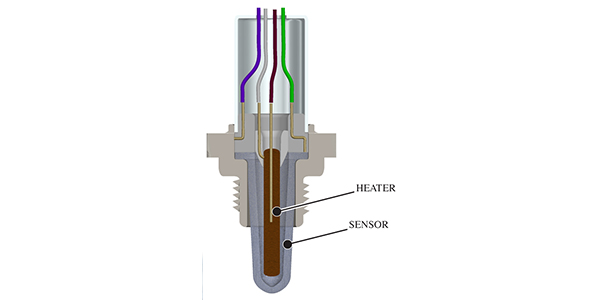
 Pulling a P0135 Oxygen Sensor Heater Circuit Malfunction (Bank 1 Sensor 1) code means you’re dealing with a possible oxygen sensor heater element and/or associated components in this circuit. This article will attempt to provide a game plan for diagnosing a vehicle with this code.
I’ve found through my research that all of the car manufacturers appear to have similar logic on how these systems may work, but I always start my process by looking to see if any feed or ground issues may exist in the circuit. A quick review of the schematic for this system shows a feed supply, A/F fuse, A/F relay, A/F sensor heater and ECM.
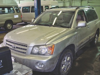
This month’s diagnostic journey begins with a Toyota product. (See sidebar below for information on a training video that offers a good perspective into the operation of these Toyota systems.)
Our subject vehicle is a 2003 Toyota Highlander 3.0L. This vehicle is set to go to emissions testing and needs the oxygen sensor heater monitor to run and pass prior to testing.
We’ll approach this process in a logical format; the Toyota Techstream software as well as the Pico lab scope will be used. It must be clear upon starting this process that the correct sensor be identified; there are two sensors at the front of the engine. One of the sensors is in plain view and can be easily mistaken as the faulty sensor.
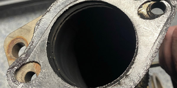
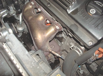 I have provided two photos (Photos 1 and 2) that show the sensors as they appear on this subject vehicle. The sensor closest to the engine firewall is A/F bank 1 sensor 1. We’ll use the sensor that was noted near the radiator as the one to compare with our suspect sensor. The
 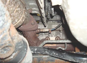 malfunction thresholds have been noted as the heater current being too low or too high. The Toyota Techstream software will first be used to confirm our trouble code information. We will also review the voltage and current information for both our heater circuits.
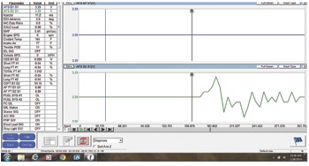
A Techstream snapshot was performed and Figure 1 notes the activity on A/F B2S1; there was no activity noted on A/F B1S1. The tool also indicated that there was a P0135 stored in the controller’s memory. I decided that I would first review the activity on A/F B2S1, as this would provide a base for known-good. 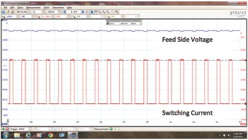
Figures 2 and 3 from the Pico lab scope show the voltage available at the feed side of the heater circuit as well as the switching activity of the current. The voltage is to be checked on the feed side and the control side of the oxygen sensor heater circuit to get the full electrical picture. 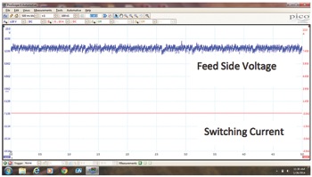
Figure 2 shows the feed side voltage as well as the switching current in the heater circuit. The voltage on the other side of the heater circuit was checked and found to be switching as well. This denoted known-good activity. Figure 2 indicates that there is a good feed, relay and wiring up to the heater circuit in one visual.
We will now take a look at our suspect sensor A/F B1S1. Figure 3 shows feed voltage going into the heater circuit and current flow in the heater circuit. There is voltage to the heater circuit; the wiring and relay are good up to that point. Note that there is no current flow in the heater circuit.
It’s now time to check voltage activity on the control side of the circuit; Figure 4 shows this 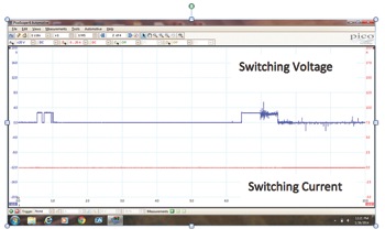 activity. Note that the ECM attempts to switch the voltage; the voltage is at a level of 4 volts. The switching then stops. There was never any current flow in the circuit. This implies an 8-to-10-volt drop across the heater element. The dynamic resistance of the heater element was too high.
The oxygen sensor was replaced and the system is now working as designed. This Pulling Codes case is now closed.
Sidebar:
Toyota, Lexus & Scion Engine Performance
It’s time to rethink the way Toyota vehicles are being repaired. These vehicles are more complex than ever and system failures have increased as OBD II models continue to age. Bizarre EVAP systems, weak but expensive catalytic converters, hard-to-test air/fuel sensors, and other high-dollar systems and components are turning Toyota diagnostics into a high-risk venture.
Here’s your opportunity to catch up on the latest information and techniques. With the Toyota, Lexus & Scion Engine Performance training video from AVI. With this extensive 3.5-hour training program, you will receive the all-new Toyota, Lexus & Scion Training Manual, which includes repair information, ATG tips and testing examples from known-good and faulty systems. Also included are live OEM and aftermarket scan tool captures, photos and lab scope captures.
For more information, go to: http://bit.ly/1b0PIDa.