When wheel speed sensors (WSS) were first installed on cars and trucks, they were typically mounted on the CV joints or differentials. These sensors were not the most accurate and didn’t start working until the vehicle reached 5 to 7 mph. These are called passive wheel speed sensors.
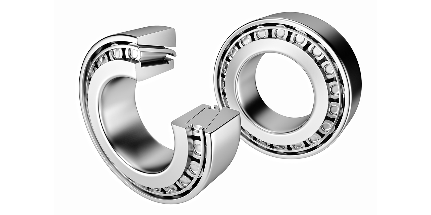
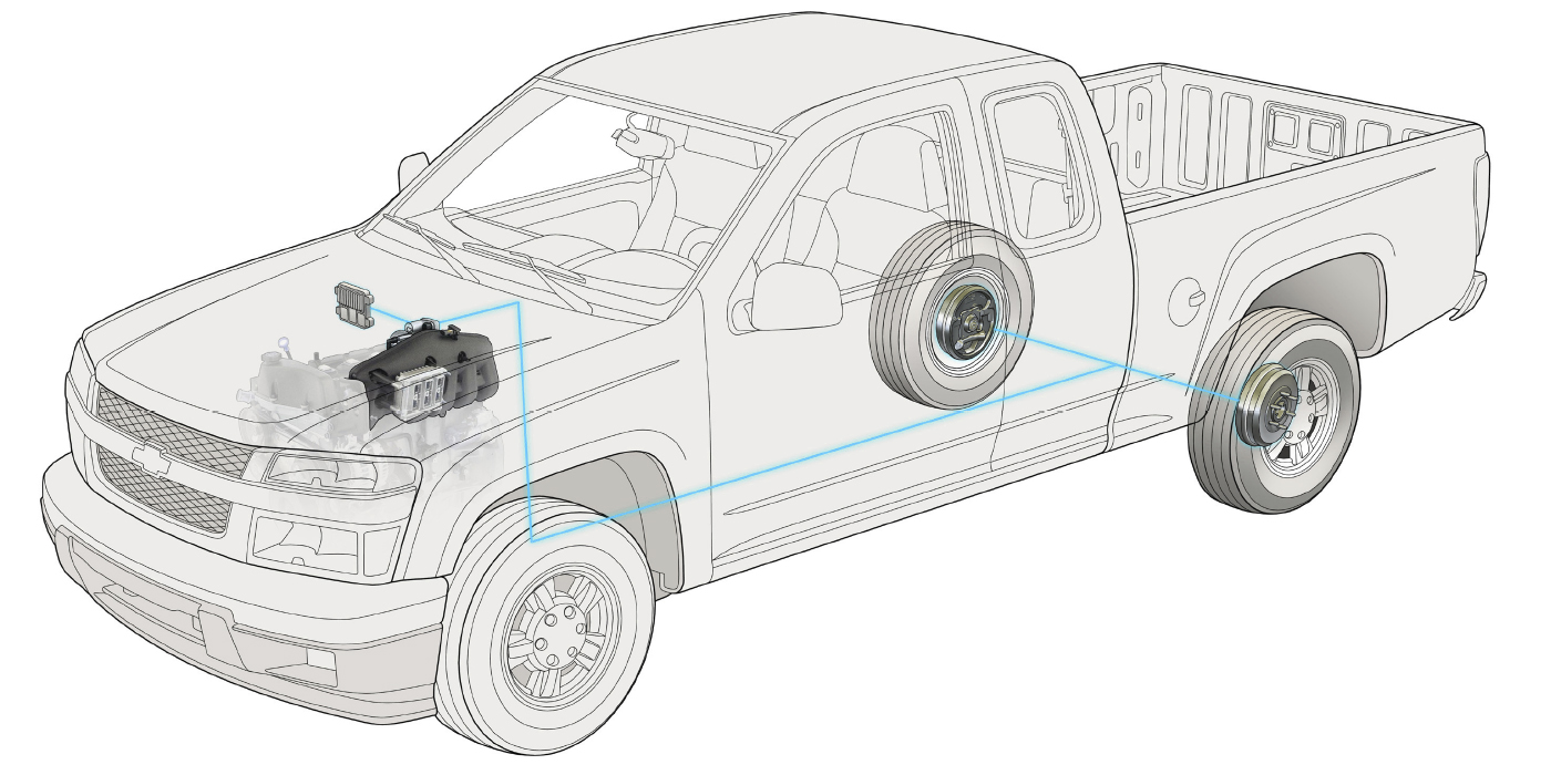
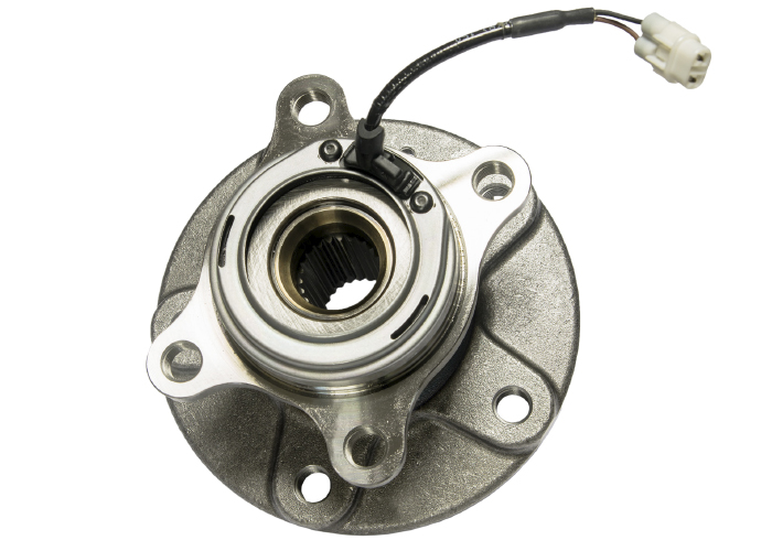
As vehicles and ABS systems advanced, the wheel speed sensors moved to the knuckles and wheel bearings. These advanced sensors can detect small amounts of movement in the wheels when the vehicle is barely moving. They are called active sensors. But, with active sensors, the inspection and diagnostic process is more challenging. Why? Because the encoder ring is moved to the wheel bearing inboard seal, and the sensor is moved to the knuckle. The only way to diagnose the sensor and circuit is with a scan tool or scope.
Scan Tools
A modern scan tool’s significant advantage is that it can graph multiple WSS outputs on a test drive. The output of the data PIDs are how the ABS control module sees the wheel speed sensors. On the test drive, take a corner to see how the speed changes between the inside wheel and outside wheel. If you notice sudden drops in speed, it is a sign that the air gap has changed due to play inside the bearing.
With a vehicle on a lift, you can observe wheel speed sensor data on a scan tool as you spin a wheel. Also, you can inspect a harness to see if poking or pulling changes the integrity of a circuit. With a scan tool, you can see changes in the values and observe if a code is set.
Even if a code is not set, you can observe conditions causing false activation complaints.
For example, if the significant build-up of magnetic debris is stuck to the tip of a sensor or the magnetic encoder ring, you can observe the PIDs for the individual wheel speed sensors. Also, you can observe PIDs for when the ABS HCU performs a correction. If the scan tool can graph multiple data PIDs, you can quickly see if a WSS does not match the other three wheels during a test drive.
With a scan tool, you see how the vehicle sees the calculated value of the wheel speeds. You are not seeing the waveform or how the WSS works with the relator wheel or magnetic encoder. For this, you will need a scope to get a waveform.
Advantages
- You can use a scan tool on a test drive.
- It shows the WSS values as the ABS module interprets them.
- Can pull freeze frame data for some ABS codes.
- Some advanced scan tools record values and replay questionable events.
- You can read and erase WSS codes.
Disadvantages
- You can’t see the actual waveform generated by the WSS using the PIDs.
- If there is an open or short in the circuit, you can’t look at the wheel speed data. This is because the ABS module will disable a circuit for a wheel speed sensor to prevent damage to the circuitry.
Scoping Wheel Bearings
Before you can start scoping WSSs, you must understand the differences between passive and active WSS and how they produce their corresponding waveforms.
Some WSS are classified as passive sensors. Passive sensors are typically found on older vehicles or used only on the rear of some newer vehicles. The passive part of their name refers to how the ABS HCU monitors the signal. In essence, the ABS module is passively observing the waveform generated.
A passive WSS generates alternating current (AC) when metal teeth or windows of the reluctor ring pass by the tip of the sensor. The sensor’s tip has a magnet wrapped in wire coils that generate the AC voltage.

More speed translates into an AC voltage waveform that increases frequency and amplitude. But at lower speeds, the WSS might not generate enough AC voltage to measure the vehicle’s speed. If there is any resistance in the WSS’s circuit, it will reduce the amount of AC voltage generated. This can cause the system to read a speed lower than the vehicle’s actual speed. This can cause a false activation complaint. But, if the resistance is too great, it will set a code and disable the ABS.
Active WSSs receive a voltage from the ABS HCU. The voltage is used by a solid-state circuit triggered by magnets passing by the tip of the active wheel speed sensor. The magnets for the encoder ring are embedded into the inboard side of the wheel bearing’s seal on most applications. The magnets are arranged so the polarities of the magnets alternate. The ABS module is actively looking for the movement of the magnets’ poles passing by the tip. The sensors can measure small movements at any speed and can even sense the direction of the rotation.
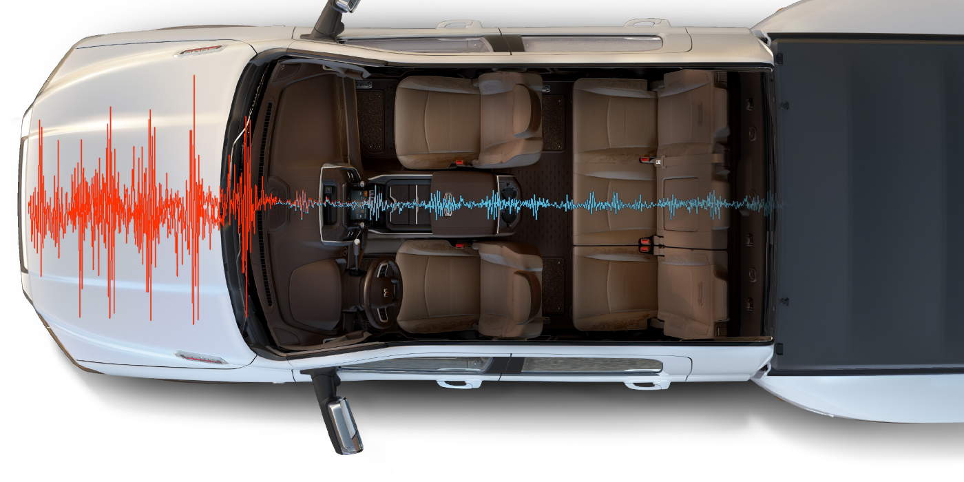
The signal generated by an active wheel speed sensor circuit is a square wave representing the magnets’ alternating poles in the encoder ring. The circuit inside the WSS switches the power on and off. The frequency of the switching is proportional to the speed of the wheel.
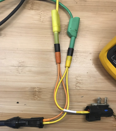
To acquire the active WSS waveform, you must create a bypass harness or back probe the circuit at the connector. The system must also be active with the ignition turned to the on position. When you connect the scope, set the scale to 1- to 12-volts. With the ignition on, you might see a straight line that hovers between 5- and 12-volts depending on the system. If you spin the wheel, you might see a very small flutter in the waveform. You will have to adjust your voltage cursors, scale and zoom to see the square wave changes that might be only millivolts.
Missing peaks and valleys can indicate damage to the encoder ring. In some cases, the magnets of the encoder ring will attract metallic debris, causing the waveform to skip between peaks and generate codes for an erratic signal.
Before you connect a scope to either passive or active sensors, you need to understand the circuit and bias voltage. The ABS module supplies voltage to the wheel speed sensor as part of a self-diagnostic procedure when the vehicle is started. The overall current levels of a wheel speed sensor circuit are low, but if the circuit is shorted to power or ground, there is potential to do damage to the circuitry in the module measuring small changes in voltage. There are no fuses in the wheel speed sensor circuit to protect the module. The module protects itself by sending out a 5- to 12-volt signal for a millisecond when it is first turned on and performs a self-check.
connector and block bias voltage signals.
If the circuit is compromised by an open or short, the increased or decreased resistance will cause the voltage to drop or exceed specifications. If the readings are not in the predicted range, the module will not supply power and will set a code and deactivate the ABS and stability control systems.
Bias voltage tests also work to detect opens in the circuit. This is why if a wheel speed sensor is disconnected it will cut power and set a code. However, when untrained technicians do not see power at the sensor, they may think the module is defective and replace it.
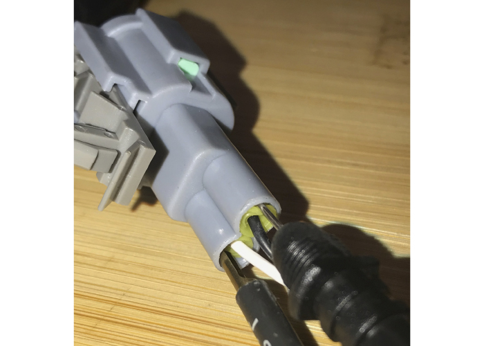
To read the voltage with the system on, you will have to back-probe a connector or use a bypass harness to clear the code from the ABS module to test the circuit.
A low current amp clamp can be used to check active wheel speed circuits. It will not be able to see with the same resolution as a voltage test, but it can confirm if the module is providing power and even a bias voltage signal. The only problem is finding a section of the harness where the two wires are divided in the wheel well.
Advantages
- You can see the actual waveform produced by the WSS sensor.
- You can use a scope to detect bias voltage.
Disadvantages
- Can’t be used effectively on a test drive.
- More labor intensive to set up connections to the circuit.
Both scan tools and scopes have their advantages and disadvantages. Both tools can help you confirm the WSS and wheel bearing condition before you remove the axle nut or replace a hub unit. This eliminates the guesswork and a possible comeback because the ABS or stability control light is illuminated.