Some 1998-2003 Golf, Jetta, Jetta Wagon and New Beetle models with 1.9L TDI may exhibit poor throttle response.
Note: Perform Steps 1 through 9. If any of these steps reveal a problem, repair or adjust as necessary and then road test the vehicle to determine if the customer concern has been eliminated prior to continuing with step 10.
Service Procedure
1. Check the engine control module (ECM) ground connection.
2. Check the injection pump timing.
3. Check the snow screen (if applicable) at the intake air duct.
4. Check the vacuum hoses.
5. Check the EGR valve and the intake manifold air flap (integrated in EGR valve).
6. Check the MAF sensor and the EGR valve, including the solenoid valve.
7. Check the crankcase ventilation system.
8. Check the engine oil level.
9. Check fuel quality.
 10. Inspect the ECM ground (GND) connection for corrosion, a poor connection or no connection.
11. Check the start of the injection pump timing. See Repair Manual, Group 23 – Diesel Fuel Injection, “Start of injection, dynamically checking and adjusting.”
Note: It’s advised to adjust to the upper range.
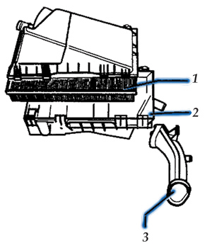
12. Check the snow screen (located below the left front fender in the air duct; see 3, Figure 1) and clean as necessary.
13. Inspect the air cleaner element (see 1, Figure 1) for proper installation. If the air cleaner element is deformed due to improper installation, this may cause the MAF sensor to fail.
14. Replace as necessary.
15. Check the integrity of all vacuum hoses and connections, and repair as needed.
16. Check the EGR valve and intake manifold air flap (integrated in the EGR valve).
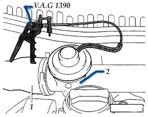 17. Remove the intake hose (see 1, Figure 2) at the EGR valve.
18. Remove the vacuum hose from the EGR valve.
19. Connect the hand vacuum pump (VAG 1390) to the EGR valve.
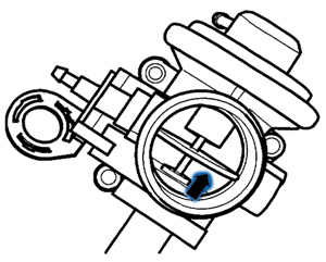
20. Apply vacuum and make sure the air flap (see arrow, Figure 3) opens and closes freely. If the flap does not open and close freely, replace the EGR valve/flap.
21. Check for correct function of the MAF sensor and EGR valve, including the solenoid valve (see the repair manual for procedure and operation ranges.)
 Note: Since both systems work closely together, when one system malfunctions, it will directly affect the function of the other. Therefore, it’s important to thoroughly follow the procedure.
22. In addition, the MAF sensor must be full-load tested. See “Evaluating measuring value blocks at full load” in the repair manual, Repair Group 01 — On Board Diagnostic (OBD).
23. Before replacing any parts (MAF sensor G70, EGR solenoid valve N18), ensure that the wiring is OK and the electrical connections are clean and functioning properly. If they are, replace the MAF sensor.
24. If the MAF sensor (G70) failed the full-load test and, after replacement of the MAF sensor, full load value still cannot be attained, check the turbocharger (consult the repair manual).
25. Inspect and ensure that the crankcase ventilation system is working to OEM specifications.
26. Check and adjust the engine oil to the proper level, if necessary (do not overfill).
27. If the condition occurred suddenly, there may be a fuel quality issue. If the fuel is suspected to be of poor quality, drain and refill with known-good quality fuel.
In most cases, performing steps 1 through 9 will restore throttle response. However, in some isolated cases, if all previous items are functioning according to specifications and the vehicle still has poor throttle response, it may be necessary to physically inspect the EGR valve and intake manifold as there may be excessive carbon buildup (greater than 10 mm) in the intake manifold and/or EGR valve (in higher mileage vehicles).
Note: While some carbon buildup is normal and is not a concern, excessive carbon buildup (greater than 10 mm) is related to fuel quality and soft driving behavior (operation at low speeds, short-distance driving, and under extremely cold and damp operating conditions).
Technical service bulletin courtesy of ALLDATA.
For additional information, visit www.alldata.com.