Models Affected: 2005-’07 Corolla and Matrix
In some cases, the cause of this DTC may be the VVT-i actuator. Use the procedures in this bulletin to verify the operation of the actuator and correct the condition.
Repair Procedure:
1. Referring to the screen flow in Fig. 1, connect the Toyota Diagnostic Tester to the vehicle and select the VVT Control Bank 1 Active Test (VVT CTRL B1) from the Active Test Menu. 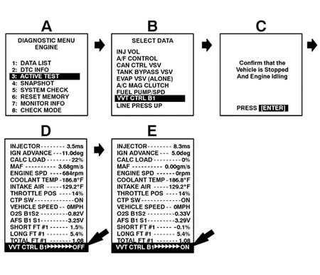
2. Using the right arrow key, toggle the VVT actuator “ON.”
3. Does the engine run rough and/or stall?
YES: Proceed to step 4.
NO: Check the oil control valve operation.
Refer to the Technical Information System (TIS):
– 2005 Corolla or Matrix Repair Manual, Engine/Hybrid System – Engine Control – “1ZZ-FE/2ZZ-GE: SFI System: Inspection”
– 2006-’07 Corolla or Matrix Repair Manual, Engine/Hybrid System – Engine Control – “1ZZ-FE/2ZZ-GE: Engine Control System: Camshaft Timing Oil Control Valve Assembly: Inspection”
4. Remove and replace the camshaft timing gear assembly. Refer to TIS:
– 2005 Corolla or Matrix Repair Manual, Engine/Hybrid System – Engine Mechanical – “1ZZ-FE/2ZZ-GE: Camshaft: Replacement”
– 2006-’07 Corolla or Matrix Repair Manual, Engine/Hybrid System – Engine Mechanical – “1ZZ-FE/2ZZ-GE: Engine Mechanical: Camshaft: Removal” 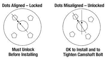
Note: The timing gear must be in the unlocked position when installing it on the camshaft.
See step 5 for instructions to unlock the camshaft timing gear.
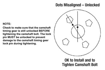
5. Identify whether the camshaft timing gear is unlocked or locked. See Fig. 2.
– If the camshaft timing gear is unlocked, it’s ready to install.
– If it’s locked, follow the steps below to unlock the camshaft timing gear before installing.
a. To disengage the camshaft timing gear lock pin, apply and hold approximately 21 psi of air pressure at the oil feed hole located 90° clockwise of the oval slot. See Fig. 3.
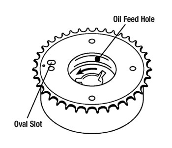
Note: The lock pin is inside the gear, not the one located in the oval slot.
b. With the 21 psi of air still applied to the gear, turn the interior assembly counterclockwise. (See blue arrow in Fig. 3.)
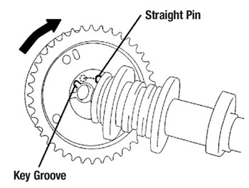
c. Install the timing gear assembly onto the camshaft with the straight pin slightly to the right of the key groove as shown in Fig. 4.
d. Turn the camshaft timing gear assembly while pushing it lightly against the camshaft until the straight pin engages the key slot.
e. Check that the camshaft timing gear is fully seated on the camshaft and that there is no clearance between the end of the camshaft and the timing gear. Install the camshaft bolt finger tight. See Fig. 4a.
f. While holding the camshaft with a wrench, tighten the camshaft bolt. Torque: 54 Nm (40 ft.-lbf.)
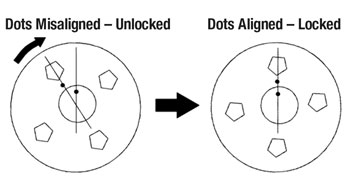
g. After torquing the camshaft bolt, rotate the camshaft timing gear in a clockwise direction while holding the camshaft stationary until the dots are aligned, thereby engaging the camshaft timing gear lock pin. See Fig. 5.
h. The timing gear is now ready for installation of the timing chain.
Note: Camshaft timing is performed with the camshaft timing gear in the locked position (dots aligned).
Courtesy of Mitchell 1.