By Ed Dorowski, ALLDATA Editor and Jeff Webster, ALLDATA Technical writer
A Saturn owner may complain about steering system leaks or noises. Refer to this Tech Tip for general diagnostic information about power steering noise and/or leak diagnosis on Saturn L-Series and S-Series vehicles equipped with hydraulic power steering.
Applicable Models:
• 2000-2005 Saturn L-Series Vehicles
• 1991-2002 Saturn S-Series Vehicles with Power Steering
Parts Information: Dye compatible with automatic transmission fluid and power steering fluid.
Service Procedure
MOAN, GROAN AND GROWL NOISES
These types of noises may be caused by insufficient or excessive power steering pump flow or system pressure, incorrect power steering fluid level or poor fluid condition or contamination.
Additionally, these different noises may be caused by air in the power steering fluid. The air may be a result of an external leak which will allow air to enter the fluid during periods of high suction from a low fluid level in the reservoir. If the fluid level is at or below the add line with the engine idling, inspect for an external leak. Possible leak areas are:
• Hoses or hose fitting O-rings;
• Pump drive shaft seal;
• Power steering gear rack ends or pinion shaft seal; or
• Seal between reservoir and pump inlet.
The system may also have a leak that allows air to be drawn in. This can occur anywhere on the return side of the system where pressures are low. In this case, the reservoir will be full, but the fluid will still contain air.
If a leak is suspected, perform the following:
Important: The presence of dust on the power steering gear does not automatically indicate a leak. Some fluid may drip onto the gear during the assembly process and will attract dust over time. A leak in the power steering gear or hoses should be suspected only if there are signs of recent fluid flow, (i.e.: fresh fluid without dust accumulation or evidence of a trail of fluid through a dusty area).
Visually inspect pump, hoses and gear for signs of leakage. In addition to visual inspection, the following diagnostics may help to locate the source of either type of leak.
Vacuum Test
Use a vacuum bleeder and J45727 Power Steering Bleeder Adapter to vacuum test the system.
Note: To prevent damage to the vacuum pump seals by the power steering fluid, always use a fluid collector between the vacuum pump and power steering pump reservoir.
1. Verify that power steering fluid reservoir is at the FULL mark. If necessary, add fluid before beginning test.
2. Attach vacuum tester (J35555 or equivalent) to the power steering stopper (J45727) with supplied hose.
3. Remove power steering reservoir cap.
4. Place power steering stopper (J45727) on top of reservoir.
5. Draw maximum of 10 psi, 20 in. Hg (68 kPa) vacuum on the system.
6. Wait five minutes.
7. Vacuum should not drop by more than 1-1.5 psi, 2-3 in. Hg (7-10 kPa).
Important: This test does not indicate the location of the leak and further component checks need to be performed to isolate the leak.
8. If vacuum does drop by more than 1-1.5 psi, 2-3 in. Hg (7-10 kPa), then a leak is present.
Dye Test
If the vacuum test indicates that a leak is present, perform the following:
Important: On L-Series vehicles with 2.2L four-cylinder (L61) engines with a direct drive power steering pump, check for presence of dye in the engine oil by removing the dipstick and inspecting with a black light. All 2000 model year L-Series 2.2L four-cylinder (L61) engines had dye installed at the time of manufacture.
Important: If the engine has had dye installed, the oil splash from the cam will make it impossible to tell if there is a leak from the power steering pump shaft seal. Traces of dye can last more than 20,000 miles (32,200 km) even with regular oil changes. Do not perform dye test if engine has dye installed.
1. Add one capful dye to the power steering reservoir. Allow dye to circulate throughout the system by turning the steering wheel side to side as the engine idles for two minutes.
2. Use the black light to check for leaks in the locations listed above in this Tech Tip. (The direct drive pump on L-Series vehicles with 2.2L four-cylinder (L61) engines must be removed to check for a leaking shaft seal since oil leaking from the pump will drain into the engine oil pan.)
Once a leak is found, perform repairs using factory and/or industry standard approved practices.
When the leak is repaired and system is bled per factory and/or industry standard approved practices, or if no leak was present, but the system still has a moan or groan noise, perform the following:
Make sure vehicle is properly supported and squarely positioned on the hoist.
• Remove or secure all of the vehicle’s contents in order to avoid any shifting or any movement that may occur during the vehicle lifting or jacking procedure.
• The lifting or jacking equipment weight rating must meet or exceed the weight of the vehicle and any vehicle contents.
• The lifting or jacking equipment must meet the operational standards of the lifting or jacking equipment’s manufacturer.
• Perform the vehicle lifting or jacking procedure on a clean, hard, dry and level surface.
• Perform the vehicle lifting or jacking procedure only at the identified lift points. DO NOT allow the lifting or jacking equipment to contact any other vehicle components.
• Failure to perform the previous steps could result in damage to the lifting or jacking equipment, the vehicle, and/or the vehicle’s contents.
Important: Place jack stands ONLY under strong and stable vehicle structures.
1. Position vehicle on hoist and raise so that the wheels are off the ground.
2. Make certain the fluid level is at or above the COLD line on the dipstick.
3. Turn engine OFF, but make sure steering column remains unlocked.
4. Use vacuum tester J35555 or equivalent and power steering stopper J45727 with the separator cup installed between the vacuum tester and stopper to pull 85 kPa (12 psi, 25 in Hg) vacuum on the system.
5. Turn the steering wheel lock-to-lock 10 times. Do this slowly so that any air in the system has time to separate from the fluid.
6. After 10 turns lock-to-lock, check vacuum pressure. If it has dropped, increase vacuum to 85 kPa (12 psi, 25 in Hg).
7. Start engine and allow to idle.
8. Turn steering wheel another 10 times lock-to-lock.
Important: This system is designed to build pressure as the fluid warms up. This pressure helps to keep the pump quiet. Before re-evaluating the system for noise, let it cool.
9. Remove vacuum adapter, check fluid level and adjust if necessary, then install cap.
POP OR CRUNCH NOISE FROM STEERING WHEEL OR STEERING COLUMN
Possible causes for pop or crunch noises that can be felt in the steering wheel or heard coming from the area of the steering column are:
• Steering intermediate shaft;
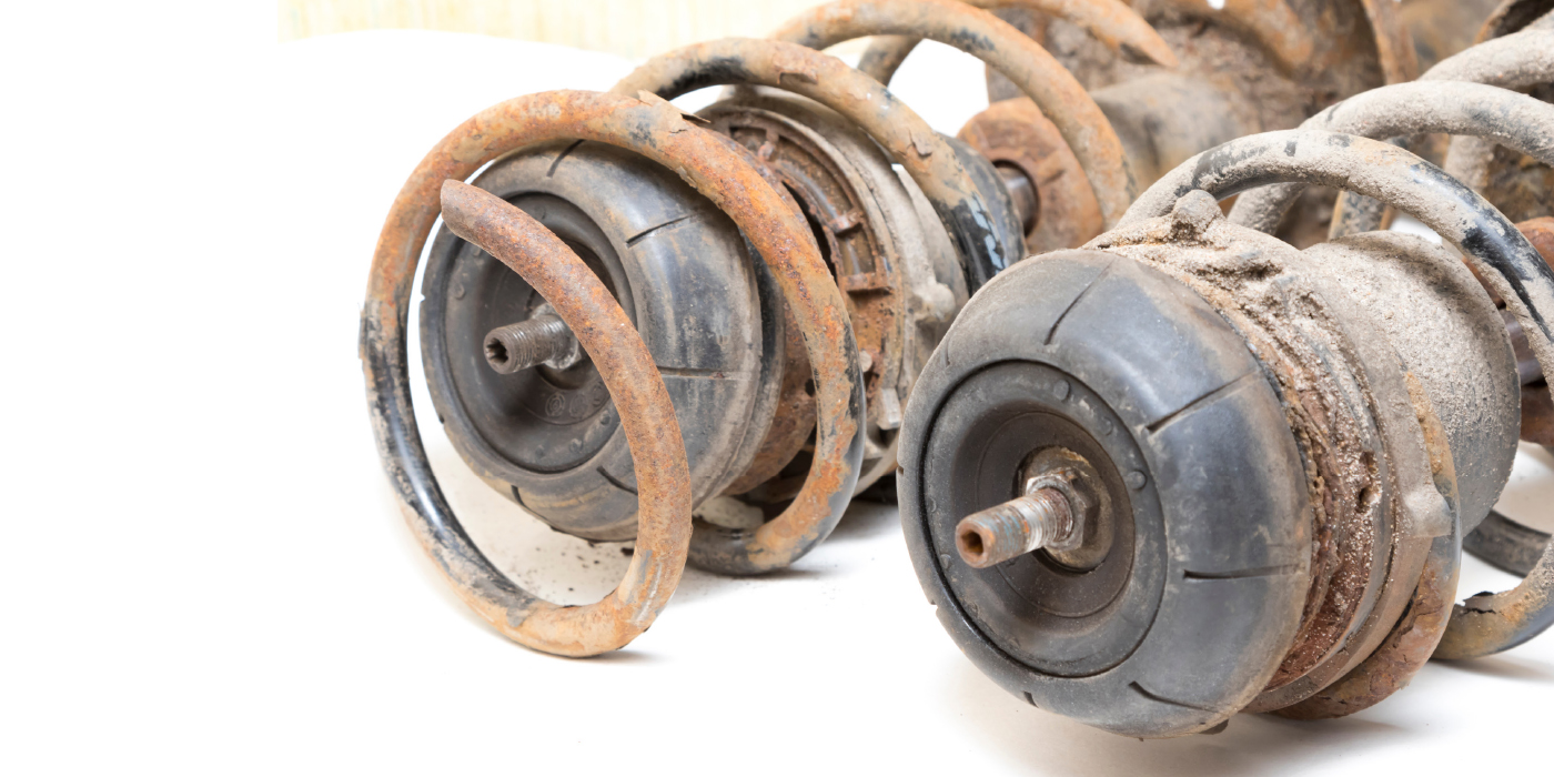
• Strut mounts;
• Tie rod ends; or
• Steering column.
Important: Ensure that the noise is not coming from another source before the power steering gear is replaced.
Power Steering Gear Diagnostic Procedure
1. Verify customer concern.
2.Use Chassis Ears J39570 (SA9217NE), or equivalent, or visually inspect to isolate location of noise.
3. Turn the steering wheel while holding onto the intermediate shaft to determine if the shaft is causing the noise.
4. Disarm the SIR (Supplemental Inflatable Restraint) system before disconnecting the intermediate shaft using factory and/or industry standard approved practices. Remove the intermediate shaft and extend and contract its length to redistribute the lubrication.
Note: Turning the steering wheel too far with the intermediate shaft disconnected will result in damage to the SIR roll coil. While intermediate shaft is removed, carefully turn the steering wheel 180°(1/2 turn) each way and check for noise. It may be helpful to restrain the lower end of the steering column and check for noise while applying torque to the steering wheel.
5. Reinstall the intermediate shaft into the vehicle and again feel and listen while turning the steering wheel.
NOTE: This Repair/Service Procedure is excerpted from a Technical Service Bulletin published by General Motors Corporation, and is intended for use by trained, professional technicians with the knowledge, tools and equipment to do the job properly and safely. It is recommended that this procedure not be performed by “do-it-yourselfers.”