Affected Vehicles: Some 1998-’99 Rodeo (UE) models and 1999 Rodeo (UE) VIN break point: 8X4351792
Some Rodeo owners may comment on the presence of steering wheel vibration or shimmy during vehicle operation at medium to high speed. A steering "nibble" may be felt in the steering wheel when driving on smooth roads (such as concrete) at highway speeds. A "nibble" may be defined as "slight rotational movement" in the steering wheel.
Note: Depending on road conditions, some vibration that is felt through the steering column, floor or seat is normal when the vehicle is driven at high speeds.
Possible cause may be one or a combination of the following:
• Tire shake and harmonic vibration due to over-inflation, imbalance and/or measured excessive tire RFV (radial force variation).
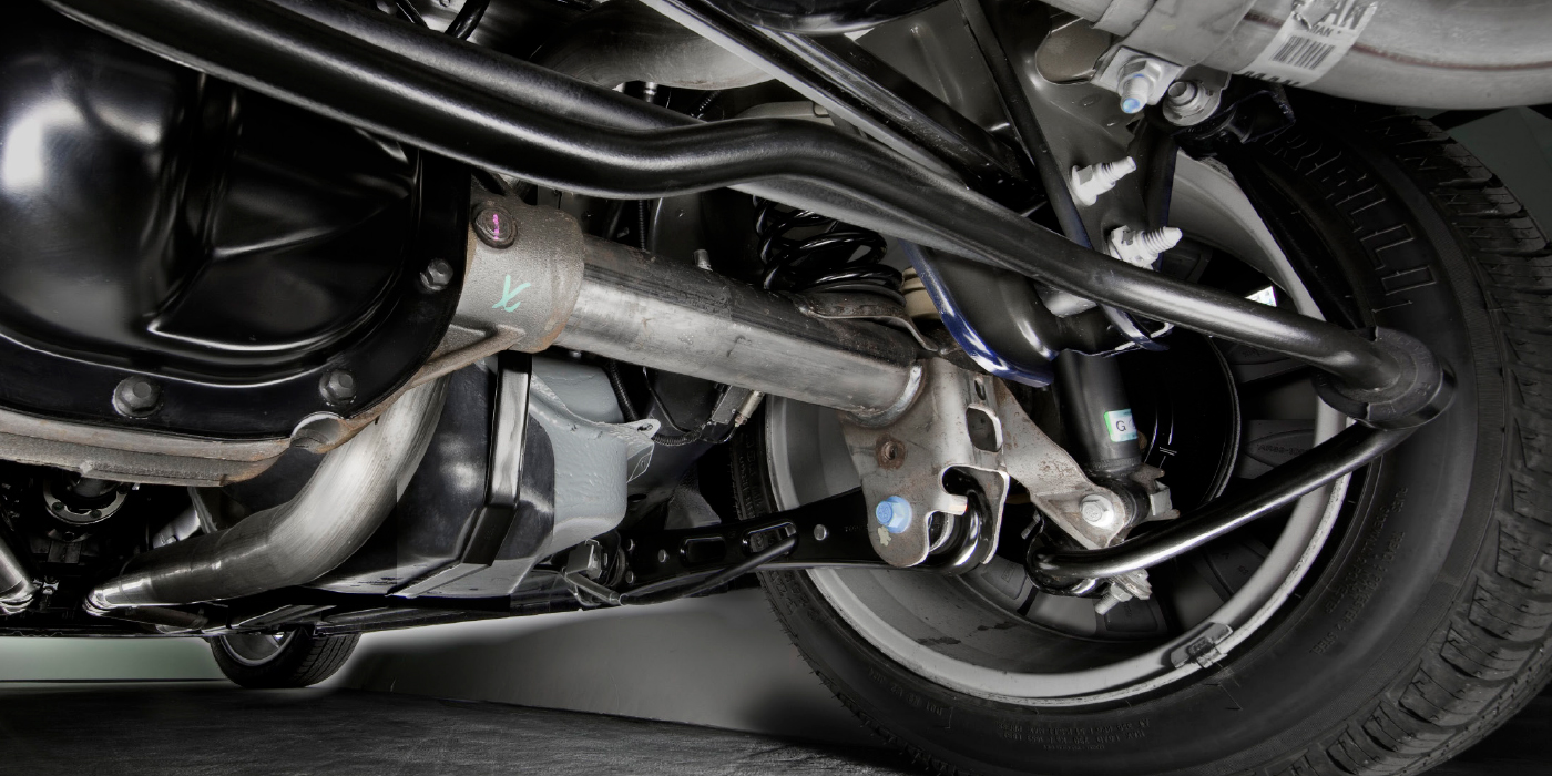
• Body vibration that is transmitted through the No. 1 body mounts (located behind the front bumper), due to insufficient isolation clearance at the upper-half of those body mounts.
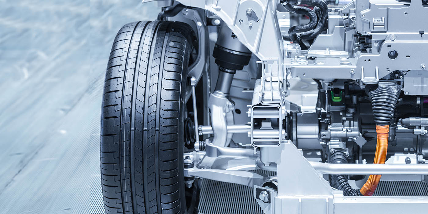
• Steering feedback from insufficient dampening which is transmitted from the steering rack assembly to the steering column.
Correction:
To correct this condition, a three-phase procedure as summarized below must be followed:
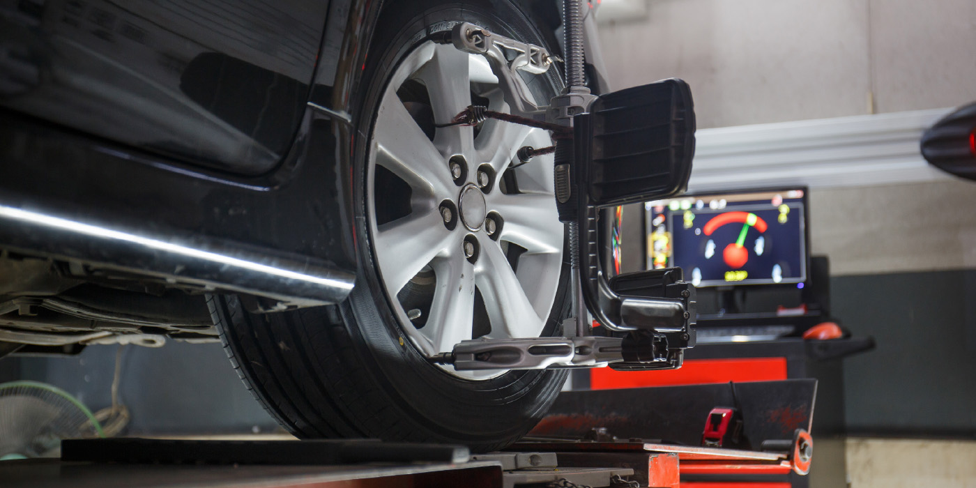
1. Tire pressure and wheel balance correction.
– Adjust tire pressure to specification.
– Rebalance all four wheels/tires (check for flat spots).
– If your shop is equipped with tire balance equipment, measure the tire RFV (radial force variation).
2. Body mount clearance inspection and correction:
– Inspect and measure the clearance gap of the No. 1 body mount.
– If necessary, install shims to the No. 2 and No. 3 body mounts to adjust the clearance gap to specification.
3. Steering yoke spring installation and steering coupling inspection and adjustment:
– Install new steering yoke spring.
– Inspect the alignment of the rubber coupling at the second steering shaft.
– If necessary, adjust the position of the steering shaft to realign the rubber coupling.
Follow the detailed description and procedure for each phase, as outlined in this bulletin.
Important: These procedures must be completed in the order listed. Failure to follow the procedure order may result in an incomplete repair.
Service Procedure
Tire Pressure and Wheel Balance Correction
1. Using the appropriate tire inflation pressure specification from below, adjust all tire pressures:
– P215/75R15 (29psi Front / 29psi Rear)
– P235/75R15 (29psi Front / 29psi Rear)
– P245170R16 (26psi Front / 26psi Rear)
Note: The above specifications are for cold tires. Tire pressure increases approximately 15% when the tires become hot during driving.
2. Using a dynamic off-vehicle wheel balance machine, rebalance all four wheels and tires.
– At this time, inspect the wheel/tire for any damage(s) that may contribute to excessive radial or lateral run-out.
– If your shop is equipped with tire balance equipment, measure the tire RFV, and correct if necessary.
3. Reinstall all wheels to the vehicle.
– Be sure to torque all lug nuts to 118 Nm (87 lb.-ft.).
Body Mount Clearance Inspection & Correction
1. Set the vehicle down on level ground. This is necessary for the correct reading of body mount clearances.
2. Inspect and measure the upper clearance gap of the No. 1 body mount, located behind the front bumper.
3. If the clearance gap is at least 2 mm or more, skip to Steering Yoke Spring Install & Steering Coupling Inspection sub-section. For insufficient clearance gap conditions (less than 2 mm gap to zero gap), continue to next step.
4. Remove the front plastic door sill plate with kick panel, and lift the carpet to remove the No. 2 body mount bolt access plug. Repeat this step for the other side.
5. Remove the rear plastic door sill plate with kick panel, and lift the carpet to remove the No. 3 body mount bolt access plug. Repeat this step for the other side.
6. Loosen and remove the No. 2 body mount bolt through access hole along with washer/nut underneath the mount.
7. Loosen and remove the No. 3 body mount bolt through access hole along with washer/nut underneath the mount.
8. Loosen the No. 1 body mount bolt and nut. Do not remove the bolt from this mount.
9. Partially lift the body away from the frame using a floor-jack, equipped with a body lifting adapter tool J-44267, under body flange rail at mid-point of front door.
Important: Lift the body only to the amount required for shim installation. Excessive lifting height with the jack may damage the body or other components.
10. Add two shims to top of No. 2 body mount bushing (between the body and mount), reinstall the body mount bolt through access hole, and hand-thread the bottom nut.
11. Add one shim to top of No. 3 body mount bushing (between the body and mount), reinstall the body mount bolt through access hole, and hand-thread the bottom nut.
12. Lower the floor-jack to allow body to rest on the body mounts.
13. Tighten and torque the No. 2 body mount bolt and nut to specification: 50 Nm (37 lb.-ft.)
14. Tighten and torque the No. 3 body mount bolt and nut to specification: 50 Nm (37 lb.-ft.)
15. Tighten and torque the No. 1 body mount bolt and nut to specification: 50 Nm (37 lb.-ft.)
16. Repeat Step 5-15 for the other remaining side.
17. Remove any body undercoating residue from your hands prior to reinstalling the interior parts. (Note: Undercoating residue is difficult to remove if stained in vehicle interior.)
18. Reinstall the following interior parts for both sides:
– All removed access plugs (4)
– Interior carpet (fit into place)
– Front and rear door sill plates and kick panels.
19. Verify the repair by re-measuring the upper clearance gap of the No. 1 body mount. Specification: At least 2 mm or greater.
Steering Yoke Spring Install & Steering Coupling Inspection
1. Adjust the steering wheel to center position.
2. Lift vehicle.
3. At the bottom of the steering rack, locate the yoke plug and clean the plug and the surrounding surface.
4. Mark and index the position of the yoke plug in relation to the housing.
5. Partially loosen the lock nut (42 mm) to loosen and remove the threaded yoke plug. This allows access and removal of the yoke spring.
6. Clean the thread face of yoke plug, apply thread sealant and reinstall with new (yellow) spring.
7. Turn the yoke plug fully clockwise to bottom-out the plug, then turn counterclockwise not more than 1/4-turn to align the index marks of the yoke plug and the housing.
8. Tighten and torque the lock nut, while keeping the original location of the yoke plug. Lock nut torque specification: 68 Nm (50 lb.-ft.)
9. For identification purposes, use a scribe and mark a "V" at the center of the yoke plug.
Part II
10. Set vehicle down on level ground.
11. Inspect the alignment of the rubber coupling at the second steering shaft.
12. If the steering rubber coupling is misaligned, continue to the next step. Disregard this section if the rubber coupling is properly aligned.
13. Loosen the pinch bolt of the steering shaft, which is under the hood and below the brake master cylinder.
14. Using a pry, adjust the coupling area to align the rubber coupling, through service cutout in left-front wheel housing.
15. Retighten and torque the steering shaft pinch bolt. Spec: 31 Nm (23 lb.-ft.)
Courtesy of ALLDATA.


