If you receive customer reports in the affected vehicles listed below of noises at the refrigerant compressor, the cause could be a defective belt pulley or belt pulley bearing. The pulley and pulley bearing can be diagnosed and replaced with the compressor still installed in the vehicle by following the below procedures.
Affected Models:
• All Model 163, equipped with M112 engine;
• All Model 163, 164 and 251, equipped with M113 engine; and
• All Model 164 and 251, equipped with M272/273 engine.
Service Procedure:
1. Locate the noise by duplicating the conditions under which the complaint occurred.
2. Before the belt pulley on the refrigerant compressor is replaced, verify that the following components in the belt drive are not the source of the noise and repair as required — alternator, power steering pump and water pump.
3. If there is also a cooling performance complaint, the noise could be caused by a low refrigerant level. Perform a refrigerant circuit test as per SDS and follow instructions for corrective actions.
4. If there is a whining noise that is RPM-dependant, that is present with the air conditioning on or off, and is determined to be caused by the tensioner pulleys, guide pulleys or refrigerant compressor, continue with step 5.
Note: The A/C compressor does not turn off immediately when A/C “off” is selected at the control module. In order to ensure the compressor is off, select A/C off, select Climate system off and select climate system on.
5. Remove the poly-V-belt from the refrigerant compressor.
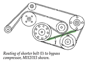 6. Install a shorter belt to bypass the compressor. Route belt as shown in Fig. 1.
• Engines M112/113 – 20 x 2315 to 2325 mm (P/N A011 997 96 92).
• Engines M272/273 – 20 x 2330 to 2340 mm (P/N A011 997 04 92).
7. Run the engine with the short belt installed. If the noise is still present, check whether the tensioner and/or guide pulleys are the source of the noise. Replace the defective tensioner and/or guide pulleys as necessary.
8. If the noise is no longer present, allow the engine to cool and proceed to step 9.
9. Replace the compressor pulley as follows.
Note: It’s not necessary to remove the compressor or evacuate the refrigeration circuit.
10. Remove the poly-V-belt. Determine if the diameter of the pulley is 100 or 110 mm.
11. Raise the vehicle and remove the lower engine compartment paneling.
12. Remove the belt pulley circlip. With plastic belt pulleys, it’s possible to insert a screwdriver under the circlip and pry it out of the groove.
13. Remove the hub using a socket and counter hold tool, W112 589 07 40 00. If you’re holding the compressor shaft stationary and turning the drive hub, loosen it by turning it counterclockwise and tighten it by turning it clockwise. If you’re holding the drive hub stationary and turning the compressor shaft, loosen it by turning it clockwise and tighten it by turning it counterclockwise. Use a small magnet to remove flat washer from the shaft. The end of the compressor shaft may break off when being loosened because the hub is constantly being tightened when the compressor is turning. If the shaft breaks off, the compressor should be replaced.
Note: There are two versions of the compressor shaft, a 7 mm hex and one with two flats. The shaft with two flats requires the use of socket W112 589 02 09 00.
14. Remove the snap ring for the pulley bearing.
15. Remove the belt pulley from the end of compressor housing.
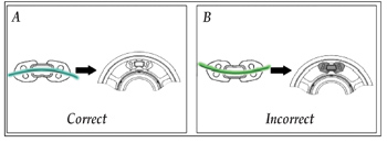 Note: Do not apply a pulling force in an axial direction to the refrigerant compressor shaft. Assemble the rubber dampers into the new pulley as shown in example A in Fig. 2. Make note of the direction of the curvature of the rubber dampers and install them over the reinforcing webs in the pulley, not in the spaces between the webs.
16. Install the new belt pulley onto the end of compressor housing. Make sure it’s the same diameter as the original, 100 mm or 110 mm.
17. Install the snap ring for the pulley bearing with its flat side facing the refrigerant compressor. Make sure the snap ring is seated correctly in the groove.
Note: Use snap ring pliers with 90° tips that have a minimum reach of 19 mm (0.75”)
18. Install the washer. Make sure it’s flat against the shoulder of the shaft.
19. Install the hub so that the drive fingers are inserted into the gaps between the ends of the rubber dampers. Screw the hub onto the compressor shaft clockwise and torque to 35 Nm. The hub continues to tighten when the compressor is in operation.
20. Install the circlip into the belt pulley. Make sure it’s seated in the groove of the pulley.
21. Install a new standard length poly-V-belt. Start the engine and verify correct belt operation.
22. Install the lower engine paneling.
Courtesy of ALLDATA.
For additional information, visit www.alldata.com.