Applicable Model(s)/VINs: 2004-’05 Mazda3 vehicles with VINs lower than JM1 BK**** ** 271699 (produced before Jan. 1, 2005)
Some vehicles may experience the following symptom(s) due to the wheel hub being out of position:
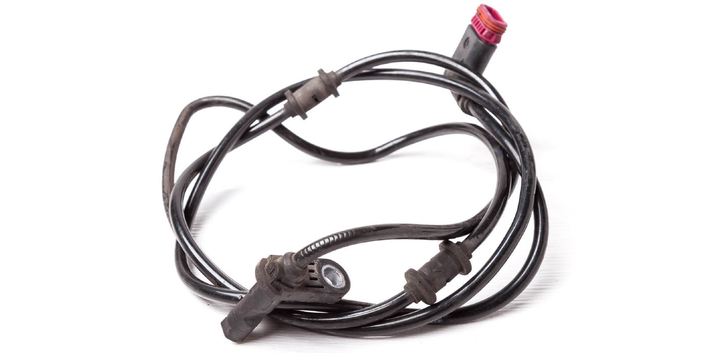
1. For some vehicles with ABS, the ABS warning light illuminates with one or more of the following DTCs stored:
• C1141 – LF ABS sensor rotor;
• C1142 – RF ABS sensor rotor;
• C1233 – LF ABS wheel-speed sensor/ABS sensor rotor; or
• C1234 – RF ABS wheel-speed sensor/ABS sensor rotor
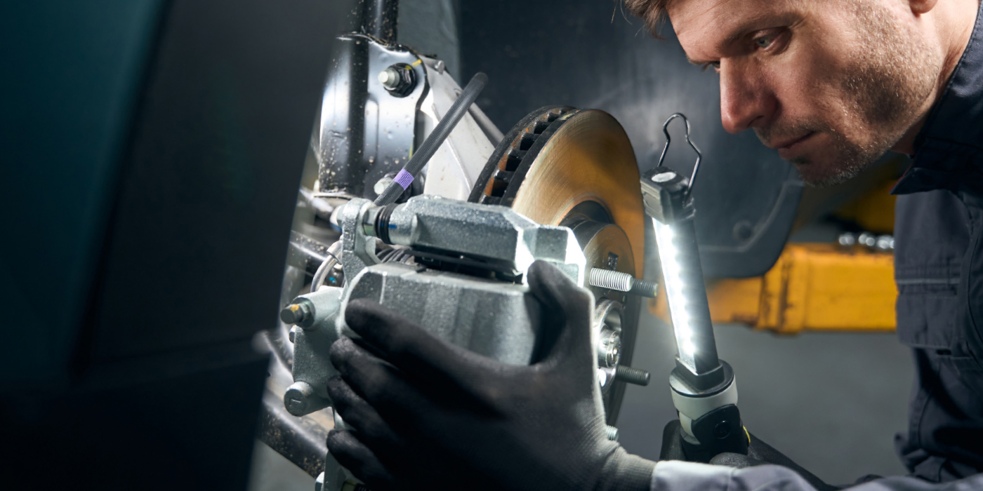
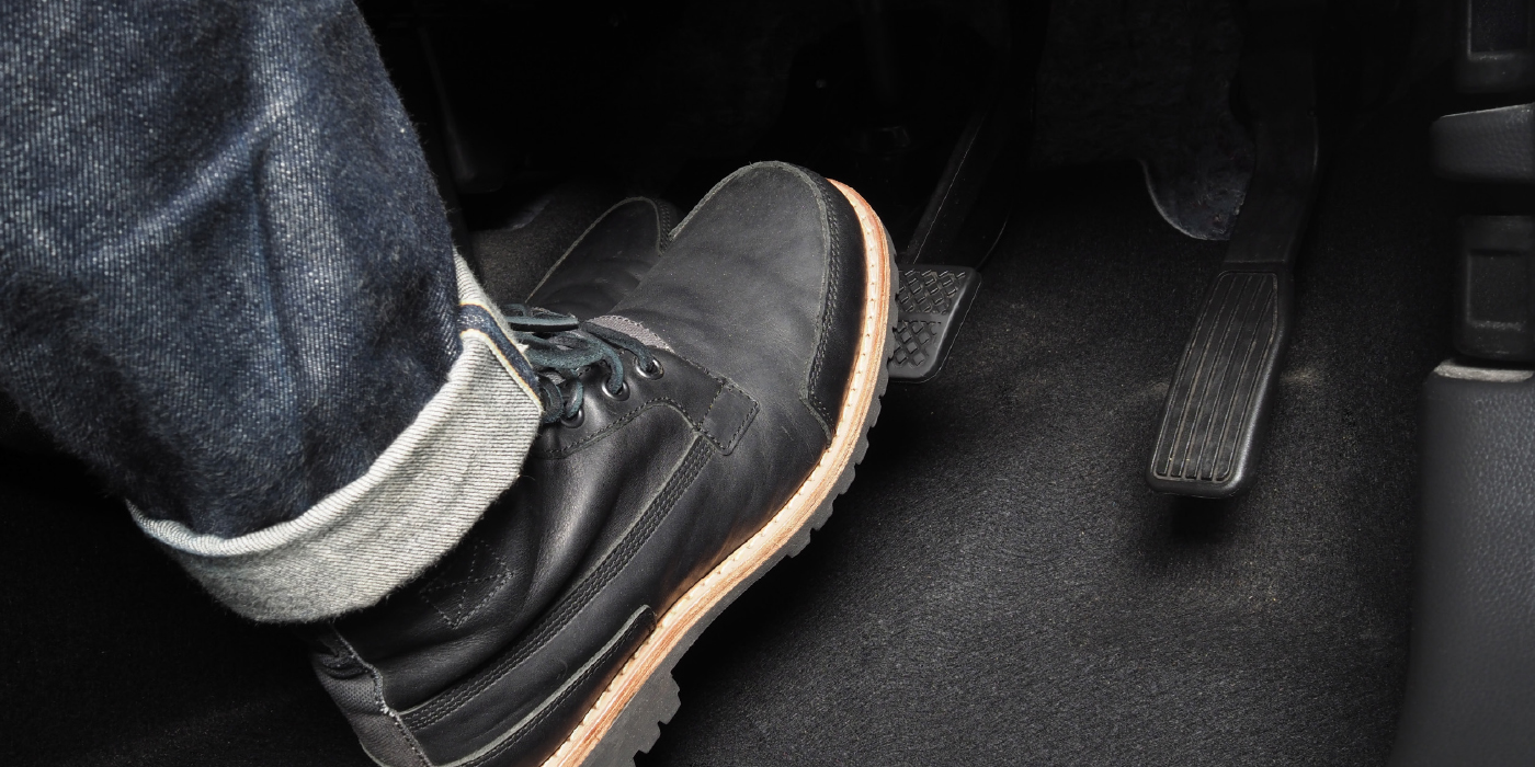
2. For vehicles with and without ABS, a continuous grinding noise can be heard from the front brake disc making contact with the caliper support. The noise can be heard without depressing the brake pedal.
The problem is the press fit between the wheel hub and steering knuckle is not strong enough, and with continued impact from the road, the wheel hub shifts in the steering knuckle. For ABS- equipped vehicles, the movement creates an excessive gap between the ABS wheel-speed sensor on the knuckle and sensor rotor in the wheel bearing, resulting in the ABS warning light coming on. For ABS and non-ABS vehicles, continued movement will lead to the front brake disc making contact with the caliper support, creating a continuous grinding noise.
Customers having this concern should have their vehicle repaired using the following repair procedure.
Repair Procedure:
Note: To perform the procedure, one of the following anaerobic adhesives (source locally) will be required: Permatex Bearing Mount for Close Fits 60940 (green), Permatex Bearing Mount for Relaxed Fits 68040 (green), Loctite 609 Retaining Compound Press Fit (green) or Loctite 680 Retaining Compound, Slip Fit (green).
1. Verify the complaint and identify if the concern is present on one or both of the front wheels.
Note: For each wheel that exhibits the concern, perform steps 2-17.
2. Remove the front wheel. 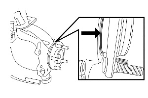
3. Unbolt the caliper housing with the caliper assembly still attached and secure the assembly so that it does not hang by the hose.
4. Remove the brake disc.
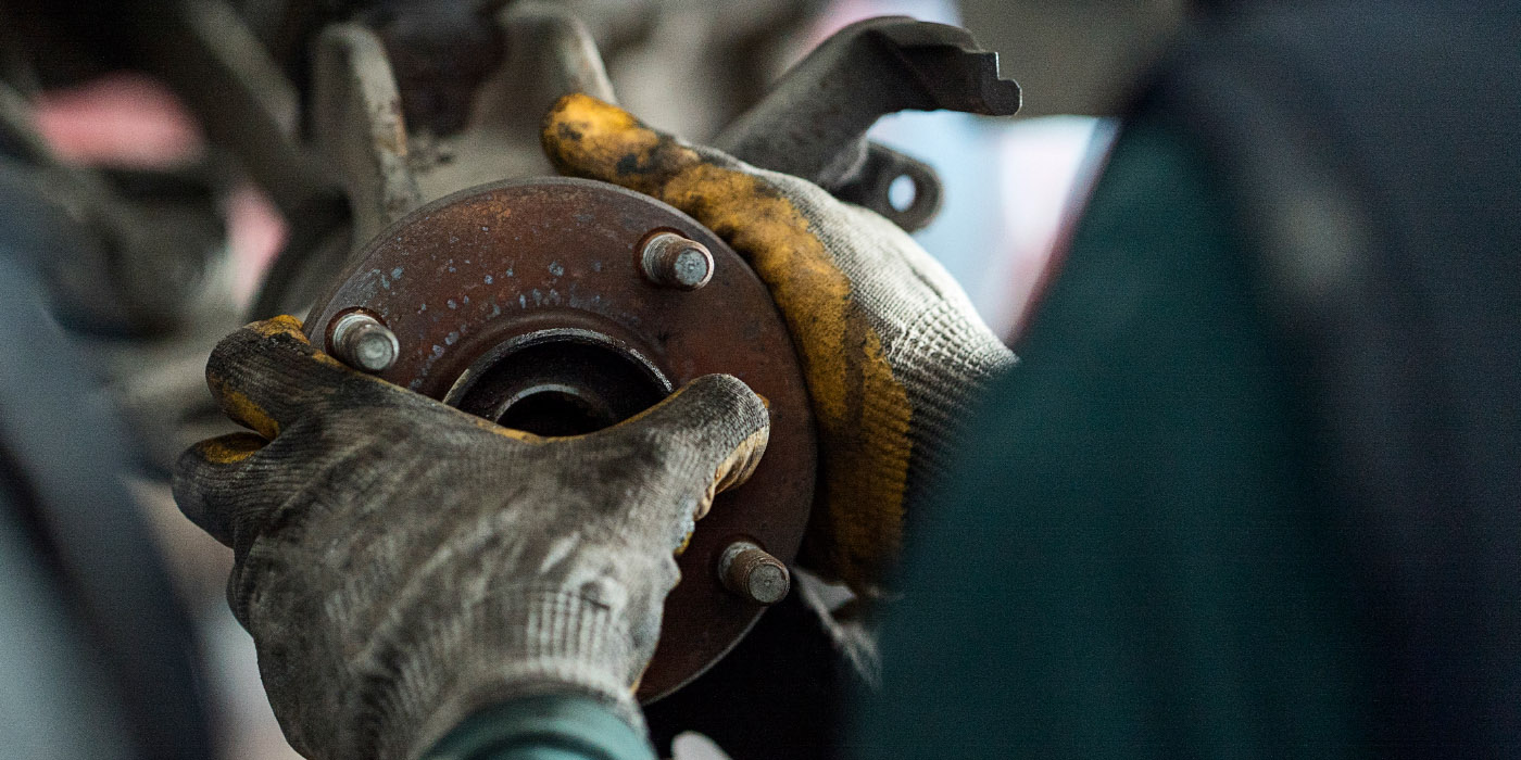
5. Visually inspect the front wheel bearing and identify if it is properly seated in the front steering knuckle. If the hub is fully seated, refer to the workshop manual to diagnose the concern, otherwise continue with this service bulletin.
Note: The hub should be nearly flush, but slightly raised from the knuckle (less than 1 mm). See Fig. 1.
6. Remove the steering knuckle assembly from the vehicle. Refer to the appropriate Workshop Manual section 03-11 – Wheel Hub, Steering Knuckle Removal/Installation. 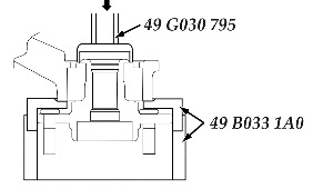
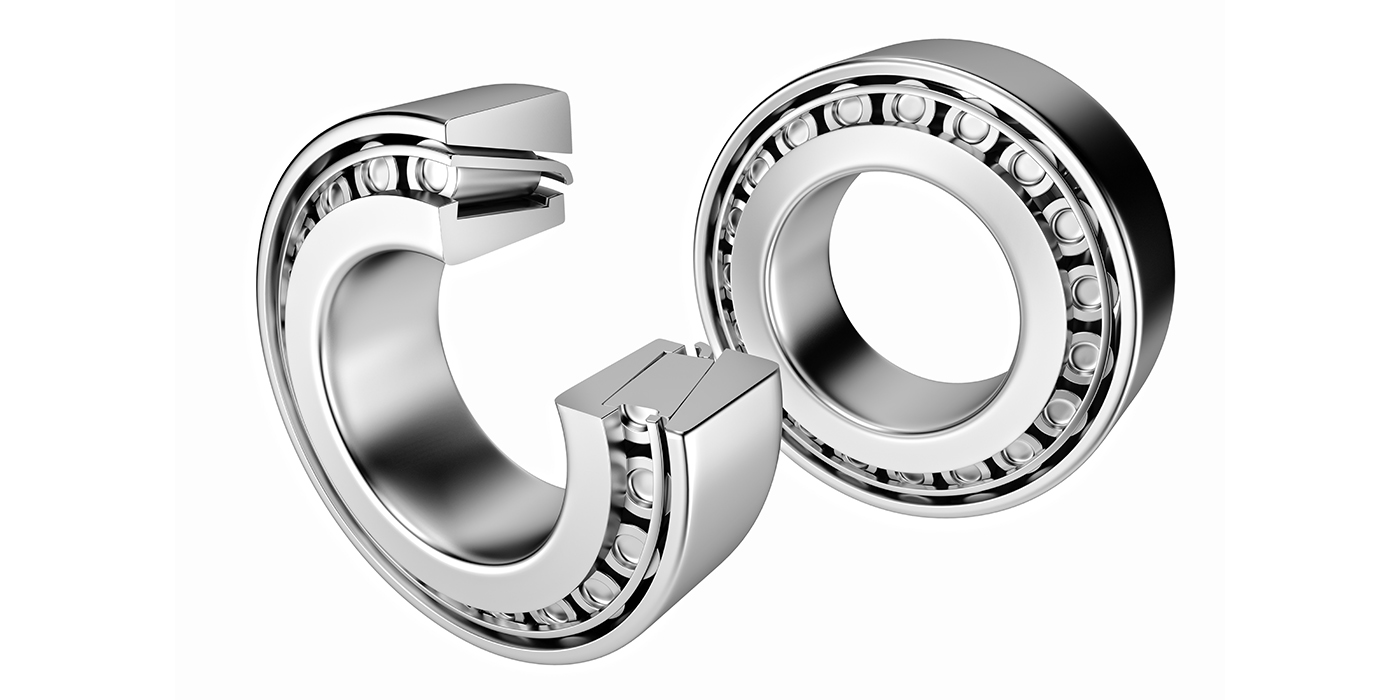
7. Remove the hub bearing assembly from the steering knuckle using a press and the SSTs. See Fig. 2.
8. Obtain a new replacement wheel bearing assembly.
9. Clean the press fit mating surfaces on the wheel bearing assembly and steering knuckle.
10. Apply the approved anaerobic adhesive to a new wheel hub component on the area that first makes contact with the knuckle during the press operation.
Note: Be sure to apply the adhesive around the whole circumference. See Fig. 3.
11. Install the new hub bearing assembly using a press and the SSTs. 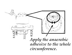
Caution: To prevent damage to the wheel hub component when pressing it down, firmly install the SST to the bearing outer race. See Fig. 4.
12. Wipe off any surplus adhesive.
13. Reinstall the steering knuckle to the vehicle as outlined in the workshop manual.
14. When installing the lockbolt:
a. Install a new lockbolt and tighten it.
Tightening Torque: 31.5-38.5 Nm (23.3-28.3 ft.-lb.)
b. Mark the lockbolt at one point and tighten it further until the marking has moved 85-95°.
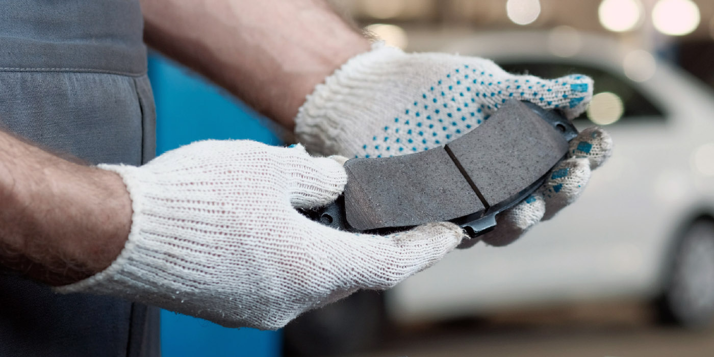
Note: If the front brake disc contacted the caliper support, replace the brake disc, caliper support and brake pads as needed.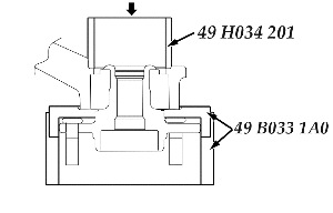
15. Reinstall the front brake disc.
16. Reinstall the caliper support; tighten the bolts.
Tightening Torque: 102-118 Nm (75.3-87.0 ft.-lb.)
17. Reassemble the remaining components in reverse order.
18. Verify the repair.
19. Perform a four-wheel alignment.
Courtesy of Mitchell 1.