Affected Models: 1986-2008 GM passenger cars and light-duty trucks with 2.8L, 3.1L, 3.4L, 3.5L, 3.9L 60° V6 engine.
Important: This bulletin only applies to 60° V6 engines. Some of the discontinued 60° V6 engine VINs and RPOs may have carried over to other new model year engines and may no longer be a 60° V6 engine. So this bulletin may not apply. It is very important to verify that the following information is correct before using this bulletin:
• Year of vehicle
• V6 engine liter size
• VIN code
• RPO
If all the information from the vehicle you’re working on can be found under the models listed above, then this bulletin applies to that engine. If one of more of the vehicle’s information cannot be found under the models listed above, then this bulletin does not apply.
Important: This bulletin does not apply to 2004-’07 Saturn VUE models with 3.5L DOHC V6 engine (VIN 4 – RPO L66) or 2005-’08 Cadillac CTS with 2.8L HFV6 engine (VIN T – RPO LP1).
If a customer comments on external oil leakage, a new design crankshaft main oil seal has been released, which incorporates features that improve high mileage durability. Replace the crankshaft rear main oil seal with the new design (P/N 12592195) using the new installation tool (EN-48108) and the following service procedures.
Important: Before you replace the new design crankshaft rear main oil seal, be sure the PCV system is operating correctly.
Note: The new seal described below comes with a protective nylon sleeve already installed in the seal. This sleeve assures that the seal is installed in the correct direction and also protects the seal from getting damaged during installation. Do not remove the protective sleeve from the seal; if removed, the installation tool (EN-48108) will not work.
The new tool has a unique design to allow the technician to easily remove the rear main seal without nicking the crankshaft sealing surface and to easily install the rear main seal squarely to the correct depth and direction.
Removal Procedure
1. Remove the transmission.
 2. Remove the engine flywheel.
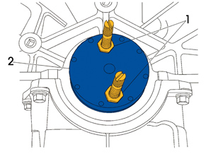
3. Install the removal plate (see 2, in Figure 1) and both threaded adjustment pins and jam nuts (1) into the back of the crankshaft flange and secure the plate with adjustment pins and jam nuts.
4. Install #2 self drill screws 38 mm (1.5”) long, eight needed, and tighten down flush to the plate.
5. Install the force screw and back off both jam nuts and continue to turn the force screw into the removal plate to remove the seal from the crankshaft.
 6. Once the seal is removed from the crankshaft (see Figure 2), remove and save all eight screws and discard the old seal.
Note: Clean the crankshaft sealing surface with a clean, lint-free towel. Inspect the lead-in edge of the crankshaft for burrs or sharp edges that could damage the rear main oil seal. Remove any burrs or sharp edges with crocus cloth or equivalent before proceeding.
Installation Procedure
Note: Never apply or use any oil, lubricants or sealing compounds on the crankshaft rear main oil seal.
1. Align the mandrel dowel pin to the dowel pin hole in the crankshaft.
2. Using a large flat-bladed screwdriver, tighten the two mandrel screws to the crankshaft. Ensure that the mandrel is snug to the crankshaft hub.
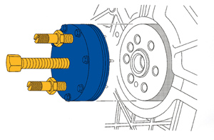
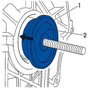 3. Install the rear main seal (see 1, Figure 3), with the protective nylon sleeve attached (2), onto the mandrel. The seal, if properly installed, will center on a step that protrudes from the center of the mandrel. To protect from errors, the seal will only fit one way onto the mandrel.
4. Install the outer drive drum onto the mandrel. Install the bearing, washer and the drive nut onto the threaded shaft.
5. Using a wrench, turn the drive nut on the mandrel, which will push the seal into the engine block bore. Turn the wrench until the drive drum is snug and flush against the engine block.
6. Loosen and remove the drive nut, washer, bearing and drive drum. Discard the protective nylon sleeve.
7. Verify that the seal has seated properly.
8. Use a flat-bladed screwdriver to remove the two attachment screws from the mandrel and remove the mandrel from the crankshaft hub.
9. Install the engine flywheel.
10. Install the transmission.
11. Inspect for proper fluid levels.
12. Inspect for leaks.
Technical service bulletin courtesy of Mitchell 1.
For additional information, visit www.mitchell1.com.