By Tom Purser, ALLDATA Editor, and Jeff Webster, ALLDATA Technical Writer
Some 2001-’03 model year Toyota Prius vehicles may exhibit a Master, Hybrid and MIL warning light on with diagnostic trouble code (DTC) P3130, information code 346 (Inverter Cooling System Malfunction). This may be caused by reduced HV water pump performance or by the design of the inverter assembly during high ambient air temperature driving conditions.
DIAGNOSIS
Follow the diagnostic procedures in this Tech Tip to determine the appropriate repair to perform based on these conditions:
Condition A:
DTC detection from a reduction in HV cooling system performance due to reduced or no water flow from the water pump. The HV water pump assembly has been improved to correct this condition.
Condition B:
DTC detection from excessive HV cooling system temperature after prolonged operation in heavy stop-and-go traffic or sustained high speeds in ambient temperatures above 90° F (32° C). The inverter assembly has been improved to correct this condition.
DTC P3125 (Converter and Inverter Assembly Malfunction) with information code 264 may also be present as a result of DTC P3130, information code 346. Do not diagnose the P3125 DTC.
DIAGNOSTIC PROCEDURE
Verify proper operation of the following systems:
• Check for coolant flow or air obstructions to the inverter heat exchanger and proper radiator seal condition. Make sure the coolant hoses are not kinked where they form turns.
• Check coolant level in the inverter reservoir tank. If the fluid is low, examine the cooling system components for leakage.
• Check for the presence of air bubbles in the cooling system.
• Confirm the proper mix of coolant and water.
• Confirm the operation of the HV coolant pump. Turbulent flow should be visible in the reservoir when the pump is operating.
After completing the checks above, proceed with one of the following:
• If any other problems are found with the HV cooling system, correct them and confirm that the DTC does not reset.
• If the pump has reduced or no water flow, follow Repair Procedure A.
• If no other HV cooling system problems are found and the DTC set while the vehicle was operated in high ambient air temperature conditions described in Condition B, proceed with Repair Procedure B.
REPAIR PROCEDURES
Repair Procedure A
Remove and replace the HV coolant pump assembly (water with motor and bracket pump assembly, P/N G9020-47022).
Note: An improperly bled coolant system can cause a repeat of DTC P3130. Refer to Repair Procedure B, Step 7 for coolant bleeding procedure.
Repair Procedure B
Remove and replace the inverter assembly with converter (P/N G9200-47071).
Caution: A repair operation incorrectly performed on the hybrid vehicle could cause an electrical shock, leakage or explosion. Be sure to perform the repair operations correctly.
• Remove the key from the ignition switch.
• Ensure that the charge connector is disconnected.
• Always wear insulating gloves.
• Disconnect the negative (-) terminal cable from the auxiliary battery.
1. Remove the service plug and WAIT 5 MINUTES before starting any repair operation (see Figure 1).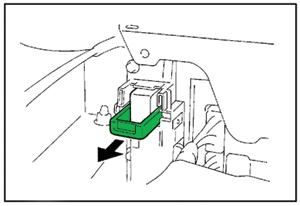
• Due to the discharge resistance, it takes at LEAST 5 minutes before the 273.6V electricity is sufficiently discharged from the capacitor in the inverter circuit.
• Even after the 5 minutes have passed, the following precaution should be observed:
Before touching a 273.6V cable or any other cable that you cannot identify, use the tester to confirm that the voltage through the cable is 12V or less.
• After removing the service plug, cover the plug connector using rubber or vinyl electrical insulation tape.
2. After removing the 273.6V cable, be sure to cover each terminal using vinyl electrical insulation tape.
3. Do not leave tools or parts (bolts, nuts, etc.) inside the cabin.
4. Remove pocket screwdrivers, jewelry or other metallic objects that may fall into the work area.
Caution: A metallic object may drop and cause a short-circuit.
5. Drain the coolant.
6. Remove and replace the inverter assembly with converter.
7. Bleed the coolant system of air (see Figure 2).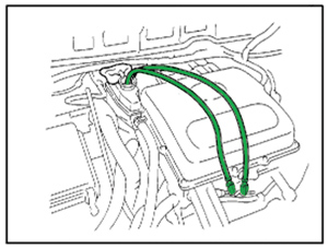
a. Loosen the bleeder plug. Attach 3-4 mm (0.12-0.16”) internal diameter clear vacuum tubing between the bleeder fitting and coolant reservoir.
• Use Toyota Long Life Coolant mixed 50/50 with distilled water.
• To prevent coolant from splashing, place a shop rag on the overflow pipe as shown in Figure 2.
b. Fill the reservoir until the coolant level in the hose connected to the bleeder plugs reaches the same level as the FULL mark on the reservoir tank as shown in Figure 3.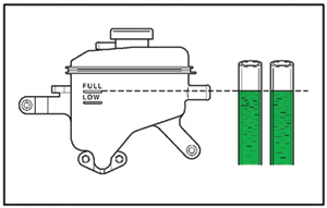
c. Tighten the two bleeder plugs.
d. Activate the water pump by turning the ignition switch to the on position. Allow the pump to operate for 20 seconds, then turn the ignition switch to the off position.
e. Loosen the two bleeder plugs to bleed the air.
f. Close the two bleeder plugs again.
g. Repeat steps D-F until the operation sound of the pump decreases and the coolant in the reservoir tank moves faster.
h. With the ignition switch on, wait for approximately 5 minutes.
i. Adjust the coolant level inside the reservoir tank as shown in Figure 4.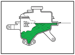
8. After replacing the inverter assembly with the converter, clear the DTC(s). Even if the master warning light is not lit, clear the DTC(s) using a Toyota Diagnostic Tester.
If a Toyota Diagnostic Tester cannot be used, disconnect the auxiliary battery for 1 minute or more and connect it again.
9. Verify operation of the inverter assembly with converter after replacement.
Depressing the accelerator pedal to a degree of 50%, increase the speed up to approximately 9 mph (15 km/h) three or four times to check that there is no problem in the inverter operation.
10. Test-drive the vehicle to ensure that all repairs are satisfactory.
Courtesy of ALLDATA.
For additional information, visit www.alldata.com.