By Omar Trinidad, Assistant Professor Automotive Department
Southern Illinois University Carbondale, Carterville, IL
Illustrating the internal operation of a voltmeter while a technician is testing a series circuit with one or two loads is a helpful way to explain how the tool works. We’ll start right off with an example.
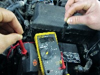
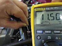
In this case, the vehicle was brought into the shop while it was raining and a puddle of water started to accumulate around the vehicle. Figure 1 shows a technician holding the red lead onto the positive side of the battery, while the black lead is being held in his other hand. The 9.26-volt reading indicates that the technician is being grounded. This strange reading is caused by the negative potential that is being detected from the negative battery post through the chassis, wheel hub, rim, tires and the puddle of water. This negative voltage potential is then measured through the technician that is standing in the same puddle of water the vehicle is in. A loss of about 2.74 volts is dropped by all the components that the potential voltage had to be measured through.
Potential Voltage Difference
There are two electrical principles that must be covered before trying to explain the digital voltmeter. The first is potential voltage difference and the second relates to circuit rules.
It is very important to understand that the digital voltmeter is looking for a potential voltage difference between the red and black leads. The number indicated by the meter is only an indication of a difference in potential. Most technicians perform an open source voltage test on a daily basis without thinking of what the meter is actually measuring. As a technician is performing an open source voltage test, the meter is measuring the difference in potential between the positive and negative side of the battery. On most automobiles, the term ground is associated with the negatively charged parts of the vehicle, such as the chassis. It is very important to understand that apart from the battery, the chassis and other grounded parts are just pieces of uncharged metal.
Most technicians place the black lead onto a ground to test for voltage at various points of the circuit. In this case, the technician is using the ground side of the circuit as a reference point and the meter will indicate a voltage reading only if the red lead detects a positive voltage. Reversing the lead connections will cause the meter to indicate a negative number. By having the black lead on the positive side of the circuit, the meter will only indicate a reading if it detects a negative voltage.
Circuit Rules
It is very rare to find a technician in the shop with a pen and paper trying to figure out an Ohm’s Law problem. However, these basic principles will aid in explaining how the digital voltmeter functions in various types of testing procedures. These rules are an observation of how a circuit operates under various conditions.
The series circuit rules are:
• Single Load Rule: The load will drop source voltage if it is the only load in the circuit.
• Multiple Load Rule: If two loads are in series, both loads will share source voltage and the load with the higher resistance will drop more voltage.
The parallel circuit rules are:
• Parallel Voltage Rule: All loads in parallel drop equal amounts of voltages.
• Parallel Resistance Rule: Total resistance of a parallel circuit is lower than the lowest resistor in parallel.
Internals
More often than not, the internal complexity of a digital voltmeter and words such as impedance or RMS often discourage technicians from fully understanding their meter.

For example, a technician must relate the impedance of the meter to a 10 mega-ohm resistor and visualize the complicated electronics as an internal voltmeter that is constantly measuring the voltage across the internal resistor, see Figure 2. Unlike most analog voltmeters, the high resistance or impedance of the digital voltmeter decreases the amount of current flowing through the meter. This allows the digital voltmeter to be used without noticeably affecting the circuit. While testing battery voltage, the meter will only draw about 1.2 micro amps on a 12-volt battery. This minute amount of current flow is too small to affect the circuit. See Figures 2 through 6.

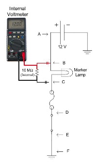
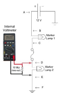
The Parallel Resistance Rule states that total resistance is less than the smallest resistance. Will the 10MΩ (ohm) resistor connected in parallel with the marker lamp affect the resistance of the circuit?
The answer to that question is yes. If the marker lamp has 5Ω of resistance and the 10MΩ resistor is wired in parallel, the total resistance will be about 4.99999Ω. This number will be rounded off and the difference will be too small for automotive purposes.
How will the reduced resistance affect the current flow through the circuit?
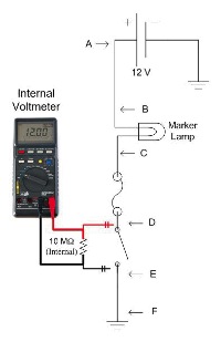
As stated above, the actual resistance of the light bulb will increase as it starts to heat up. However, to answer the second question, the hypothetical current flow will change by about 0.2 microamps (µA). The 0.2µA change is insignificant to the circuit or the test.
How will the reduced resistance and increased current flow affect the voltage drop of marker lamp 2?
As some might guess, the affect of the meter on the voltage drop of marker lamp 2 will be minimal. It will change it by about 77.9 microvolts (µV). This example proves that the high impedance of the digital voltmeter enables the meter to test the circuit with minimal influence.
Strange Readings
Strange readings, also known as ghost voltages, are measurable voltages that cannot be used. These readings can be caused by a voltage leak through a transistor, induced voltage from another wire, high resistance in the circuit, or an incorrect testing procedure.
The main problem arises when the technician holds the leads onto a wire or a T-pin. See Figure 7. In this scenario, the voltmeter can mislead the technician into thinking that the meter has found a good ground. This problem occurs in certain scenarios when the technician is touching a grounded part while testing the circuit. There are ways that a technician can touch a grounded part, such as through a part that has some physical connection to ground through a medium such as coolant.
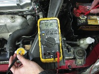
It’s very easy to touch a grounded part while testing with the voltmeter. The technician shown on Figure 8 is illustrating how a ground can be found through the radiator cap. A technician will also find ground if he or she touches the radiator cap with his arm while holding the black lead onto a T-pin and touching the red lead on the positive side of the battery.
The negative potential is actually being detected from the coolant which runs through the engine block. In some cases, the voltmeter measurements are not full source voltage because the technician or the grounded part is actually dropping some of the voltage. In either case, the meter is in series with the technician and the part that the technician is touching.
An indication of any voltage means that the meter is able to measure some sort of potential difference. This measurement is potentially confusing because it might lead the technician to conclude that there is a problem with the ground side of the circuit. However, it is very important to note that the meter is only measuring potential difference. It does not indicate if current can actually flow through. Voltage is only useful if it can push current through the circuit.
Overall, the voltmeter is only as good as the technician. The voltmeter can display a number, but the number is meaningless if the technician cannot understand what the meter is indicating. This simplified explanation of the voltmeter, along with basic electrical principles, will help the technician understand the numbers displayed. Furthermore, proper testing procedures and an understanding of the displayed values should lead to successful diagnosis and repair.