Cause and effect. That will be the theme of this article and you will hear it more than once. Without having an understanding of this relationship, it will be hard to reduce or eliminate reoccurring pulsation complaints.
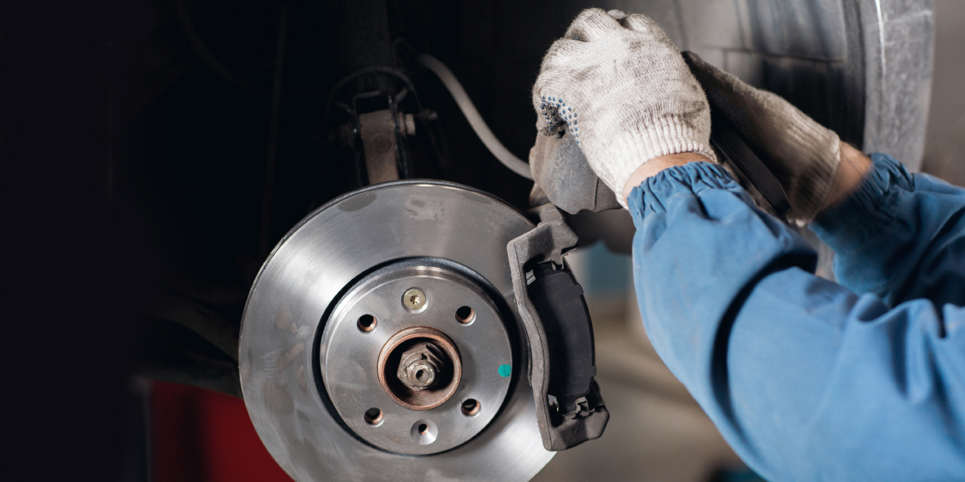
Reoccurring pulsation complaints are perhaps the second most common reason a customer returns after having brake service. The brakes operate normally for the first 3,000 to 6,000 miles, but then the customer notices a high-speed pulsation when getting off the exit ramp on his way to work one morning. The customer returns to the shop with the pulsation complaint and leaves with usually one of two “fixes” — the rotors being machined or replaced. The usual explanation given the customer is that the rotors “warped.”
Yet, too many of these same vehicles come back with the same problem. This has led many shops to lean towards installing only new rotors when this problem occurs. They do this even if the old rotors have enough material to allow machining because the shop is blaming the warping on heat dissipation. The theory goes: If I put new rotors on they will be the thickest I can get so I will have the best chances for fixing the problem. Unfortunately, the shops installing new rotors have a higher success rate than the shops machining the rotors. This has reinforced the theory of thickness, heat and warping.
To have a positive impact on this problem, we have to get away from this theory. The majority of reoccurring pulsation complaints have nothing to do with warping and heat dissipation. They are the result of cause and effect. Understanding the critical dimensions of a rotor will help understand this cause and effect. Here is a description of the important dimensions of a rotor.
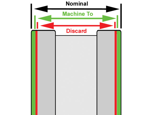
Nominal Thickness:
Nominal thickness is the thickness of the rotor when it is new (Figure 1). This thickness is not usually used on a daily basis, but is listed in most specification books.
‘Machine to’ thickness:
This is the thinnest a rotor can be machined to and still be put back into service. The purpose of having a machine to thickness is to provide enough rotor material to last the life of one set of pads. The assumption is that if the pads are replaced and the rotors are over “machine to” they should not experience enough wear to allow them to go below discard thickness through the life of that set of pads. The average difference between nominal and machine to thickness is .050” to .060”. The typical difference between machine to and discard (explained below) is .015”. See Figure 1.
Discard Thickness:
The discard thickness of a rotor is the thickness at which the rotor should be replaced (Figure 1). The common understanding of the definition of discard thickness is that it is a heat-related dimension. It is generally understood that if a rotor is at or below discard thickness, it cannot dissipate the heat generated. This is not correct. Discard thickness is the thinnest a rotor can wear to so that in the event the brake pads wear to nothing, the caliper piston won’t fall out of the caliper housing. It has nothing to do with heat. See Figure 2.
This definition makes sense if you apply it to what most technicians have experienced over the years. The average technician has serviced many vehicles with a rotor at or below discard and the vehicle stopped fine. The technician usually doesn’t know the rotor is at or below discard until they measure the rotor and compare the measurement to the specifications.
Parallelism (Disc Thickness Variation, DTV)
The two friction surfaces of a rotor are designed to be parallel to one another within a certain specification. The allowable tolerance is known as parallelism. It is also known as the rotor’s disc thickness variation or DTV (we will use DTV for the remainder of this article). See Figure 3.
You might be asking why I did not include runout in the list of rotor conditions described above? We are saving runout for last is because it can involve more than just the rotor.
Runout
Runout is defined as the amount of lateral (side-to-side) movement of the rotor as it rotates 360 degrees. The specification is usually provided as “TIR” or “Total Indicated Runout.” TIR is defined as the runout measured on the vehicle or installed runout. TIR includes all factors that can influence the amount of runout. These include:
• Runout in the rotor itself;
• Hub runout;
• Cleanliness of the hub to rotor; mating surface; and
• Wheel lug torque.
You could also call TIR the stacked runout of the hub/rotor/wheel assembly. All of the above factors add up to give the rotor’s TIR. This brings up an important point. The average allowable TIR specification for late-model vehicles is between .001” and .003”. This is the maximum allowed!
Having this important information, we can get back to the cause and effect. Many technicians are under the impression that a “warped” rotor is one that has too much runout. They also attribute this “warping” to why the brake pedal pulsates. This is not true. Runout will NOT cause pedal pulsation in most cases. This is true if:
• The vehicle is equipped with floating or sliding calipers and the caliper housing is free to move; and
• The runout is not excessive
Under these conditions, the caliper will “follow” the runout. The caliper housing will move in and out in relation to the runout. This movement will not cause the caliper piston to move. This is a key point to understand. No piston movement results in no fluid movement in the hydraulic system. If there is no fluid movement, the brake pedal won’t move or pulsate. So, a key point to understand is runout generally does NOT cause pulsation. This statement is not true if:
• The caliper housing is not free to move;
• The vehicle is equipped with fixed calipers; or
• Runout is excessive
If a vehicle equipped with floating or sliding calipers has a slider problem which prevents the caliper housing from moving, runout can cause pulsation. The caliper piston will move in and out as the rotor rotates resulting in fluid movement and pedal pulsation. Likewise, fixed caliper vehicles are sensitive to runout induced pedal pulsations.
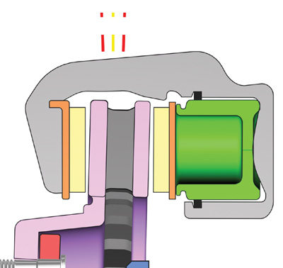
Fixed calipers (see Figure 4) have pistons on both sides of the rotor due to the stationary caliper housing. Excessive runout will cause piston movement and can result in pedal pulsation due to the runout.
Excessive runout can also cause what some people want to call pulsation. The first thing you might have noticed is I did not define “excessive.” The reason is it varies with vehicle and brake system, but generally anything in excess of .010” will start to be felt in the vehicle. It usually doesn’t feel like the traditional pulsation, instead it causes a surging feeling at lower speeds. The pulsation being discussed in this article will be a high speed pulsation occurring at speeds above 30 mph.
Runout & Pulsation
If runout doesn’t cause pulsation, then what relationship does runout have to pulsation? The answer comes in understanding what runout does cause on many vehicles.
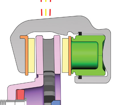
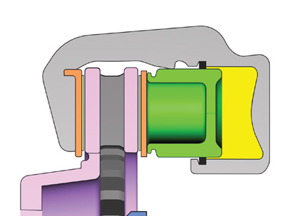
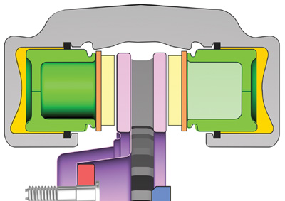
Figures 5 and 6 show an exaggerated view of a caliper/rotor assembly with excessive runout. Figure 5 shows the high spot of the runout while Figure 6 shows the low spot.
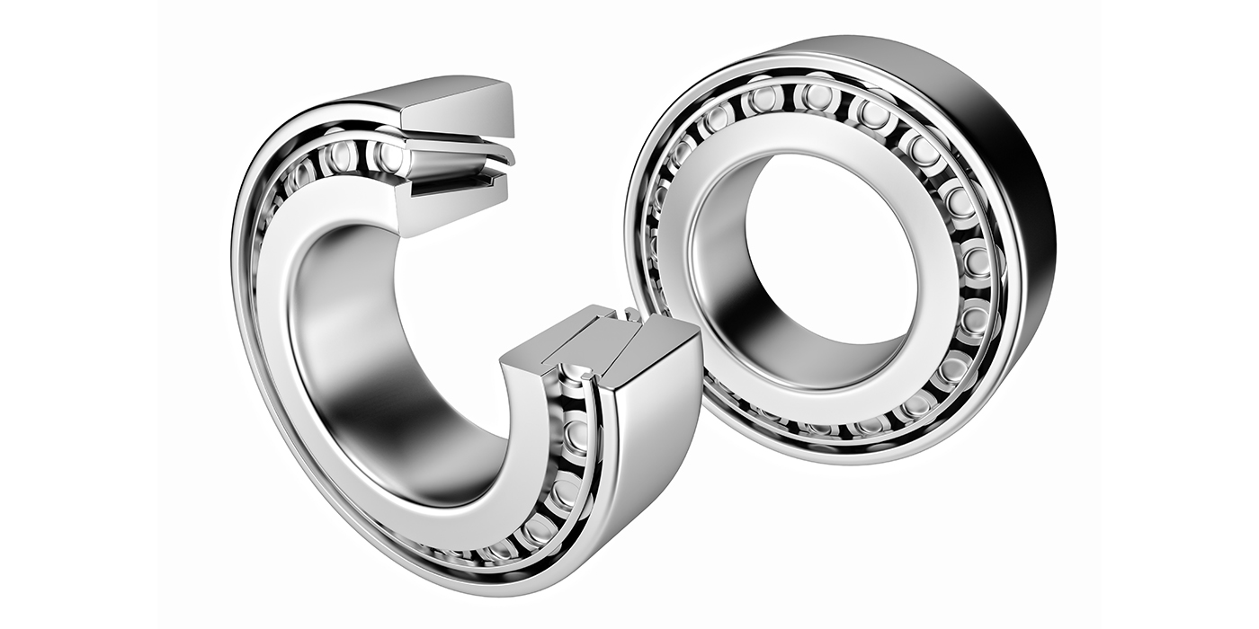
You might notice that the vehicle being shown is also of the unitized bearing type. The vehicles most susceptable to reoccurring pulsation are those that use this type of bearing. Unitized bearings are preloaded and have zero play. No wheel bearing play results the runout being “seen” by the brake pads with every revolution of the rotor. The result is the high and low spots, shown in Figure 5 and 6, scrape the brake pads with every revolution of the rotor. This scraping occurs during not only during braking, but also non-braking.
The long-term result of this scraping is the DTV (Disc Thickness Variation) we discussed earlier (See Figure 3). Pedal pulsation is the symptom of excessive DTV. The alternating thick and thin spots of the rotor cause the caliper piston to move in and out as the brakes are applied. The caliper piston moves out on the thin spots and in on the thin spots. The piston movement causes brake fluid to move in the hydraulic system and results in corresponding brake pedal movement in the form of a high-speed pedal pulsation.
Delivering vehicles with too much runout causes the majority of pulsation complaints. The effect of too much runout is the creation of DTV over time. The result of excessive DTV is high-speed pulsation. How fast the pulsation complaint shows up will depend on a number of factors. They include:
• The amount of TIR;
• The allowable TIR;
• The allowable DTV; and
• The clearance between the brake pads and rotor’s friction.
The relationship between the above factors determines whether you end up with a vehicle back in 3,000 miles or one that hits your door at 6,000. Now, these numbers aren’t cast in stone. Runout-induced DTV can show up in less than 3,000 miles and at intervals in excess of 6,000 miles. This range seems to be the norm. It is easy to see the following relationships:
• The greater the amount of installed runout the faster the problem will show up;
• The lower the vehicle’s specification for TIR is the more sensitive it will be to runout induced DTV;
• The lower the vehicle’s specification for DTV is the faster the problem will show up; and
• The closer the brake pads are to the rotor’s friction surface, the lower the amount of installed runout needed to create DTV and the faster it will occur.
There are a lot of variable, involved so the end result varies with each vehicle, but one constant remains – runout in excess of allowable tolerances causes DTV which results in high speed pulsation complaints.
So, what is in excess of allowable tolerances? It is considered anything in excess of the TIR specification provided by the manufacturer. On domestic OEM vehicles, the generic specification for TIR is .002”.
Do you want to take a guess how many vehicles leave shops with one or more rotors in excess of .002”? Too many. This is easy to understand if we look at what can cause runout during the brake service process.
Bench lathe induced runout
Bench lathe induced runout is a leading cause of runout induced DTV pulsation comebacks. There are three main reasons for bench lathe induced runout. They are:
• Arbor runout;
• Adapter condition; and
• Not verifying accuracy of setup.
All rotors machined on a bench lathe should be scratch cut before machining. This is necessary to verify the accuracy of the lathe setup. Skipping this step can lead to machining runout into the rotor. The process of verifying the setup is commonly referred to as “Scratch Cut”.
1. Position the bits approximately 1/2” away from the outside edge of the rotor.
2. Bring the outside bit in until it just touches the rotor. While holding the outer knob, place the inner dial on zero. On lathes without this feature, take note of the dial reading.
3. Back the cutting tip away from the rotor a small distance and turn the lathe off.
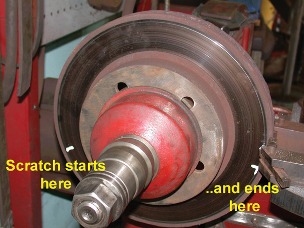
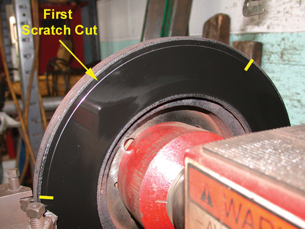
4. Observe the scratch cut. If the scratch cut is at least 50% around the rotor, proceed with the machining process (Figure 7). If the scratch cut is less than 50%, the setup needs to be verified (Figure 8).
5. Two things will cause a scratch cut of less than 50%. The first is the rotor has runout and needs to be machined.
6. The second is a problem in the setup. Adapter cleanliness, arbor runout and tightening of the arbor nut are the main causes of setup problems.
7. To verify the setup, loosen the arbor nut. While holding the inner and outer adapter rotate the rotor 180º. Retighten the arbor nut. This process changes the relationship of the rotor and adapters.
8. Turn the lathe on and then move the twin cutter in or out a small distance.
9. Make a second scratch cut by turning the dial to zero. On lathes without this feature, turn the dial into the same number as the first scratch cut. This process makes each scratch cut the same depth, which makes comparing the cuts easier.
10. Back the cutting tip off a small distance and turn the lathe off. Compare the two scratch cuts. If the problem is in the rotor the cuts should on top of one another (Figure 9).

11. A setup problem will cause the second cut to be in a different position from the first (See Figure 10).
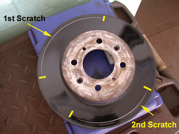
If this is the case, disassemble everything and check for cleanliness, correct adapters and for nicks on the mating surfaces. Do not proceed with the machining process until the scratch cuts are in the same position. Doing so will induce runout into the rotor.
Hub Cleanliness
The next factor that can influence the installed runout is the cleanliness of the hub. Installing a new or properly machined rotor against a dirty hub will be a waste of time.
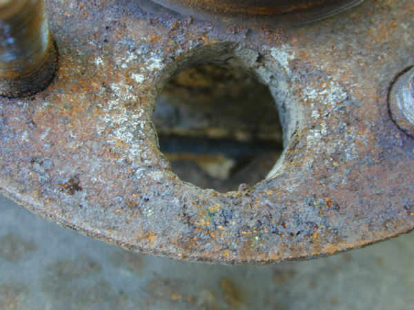
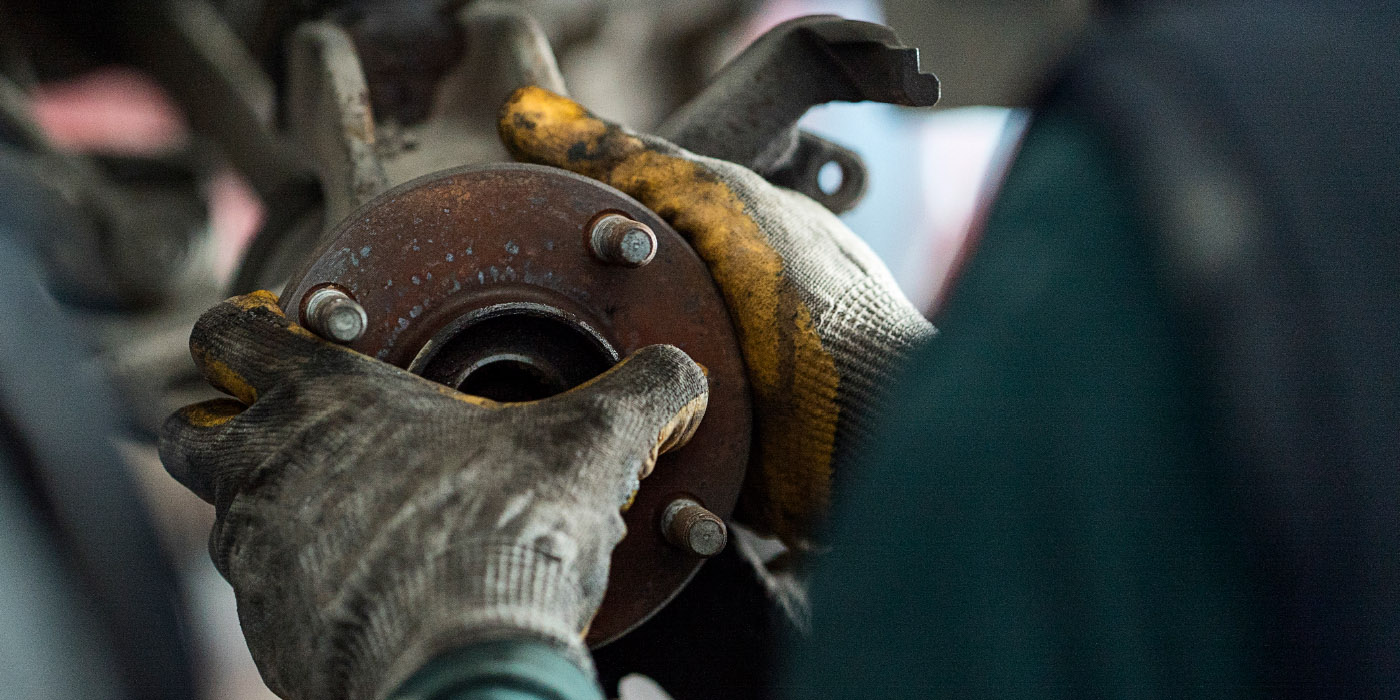
Rust on the hub’s mating surface is a leading cause of runout (See Figure 11).
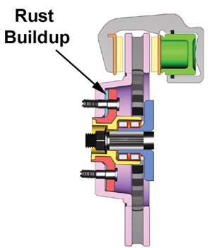
The rust can form to a point where it actually pushes the rotor away from the hub even with the wheel bolted on (See Figure 12).
This process has been termed “jacking.” It works much the same way as a tree root under a sidewalk. There are tremendous forces involved as the rust “grows” between the rotor and hub.
Cleaning of the rotor and hub’s mating surfaces is a critical part of the brake job. The hub-to-rotor mating surface must be free of rust or runout induced DTV can occur shortly after the brake job. As little as .001” of rust at the outside edge of the rotor will result in .002” to .004” of runout when measured at the outside edge of the rotor.
The method use to clean the hub will depend on the severity of the rust buildup. The hub’s mating surface can be a difficult surface to clean due to the wheel studs.
The area between the wheel stud and hub-centering flange is the most difficult area to gain access to. Here are the best methods to clean the hub’s mating surface.
Method 1 – Mild rust build up:
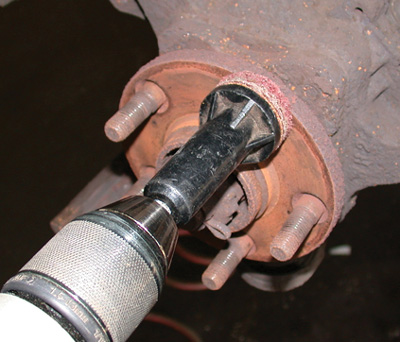
1. Use an angle grinder equipped with a scotch brite disc to clean the majority of the surface area. Get as close to the studs as possible and change the disc when needed.
2. Finish the process by using the tool shown in Figure 13 to clean the area around the studs. This tool fits over the wheel stud to allow easy cleaning of the hard to reach area of the hub.
Method 2 – Severe rust buildup:
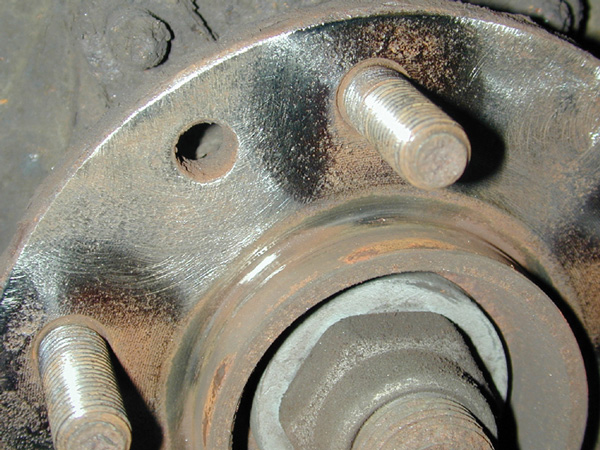
The hub shown in Figure 11 will not be able to be cleaned effectively using the steps outlined above. The end result would look something like Figure 14.
The stud cleaning tool does NOT work on mild to heavy rust. It has a tendency to polish the rust instead of removing it. The most effective method is to use the steps below.
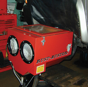
1. Abrasive blasting is the most effective method for rust removal. There is a specialized blast cabinet available that allows cleaning of the hub while it is still on the vehicle. The tool uses a drawstring boot to allow the unit to be used on the vehicle, as shown in Figure 15.
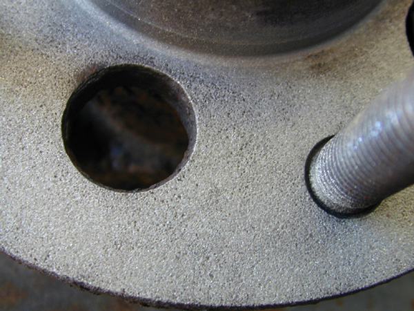
2. Figure 16 shows the finished product. This is the same hub shown in Figure 11. This hub will not be the source of rust induced runout.
While there are other methods that can be used to clean rusty hubs, the method described above is the most effective. Other methods can be time consuming, yield a lower quality job and may not result in all of the rust being removed.
Once the hub has been cleaned, the rotor can be installed. At this point in the process, a decision has to made. The decision involves whether you will measure the installed runout or not. Most shops never measure installed runout. This can be one of the reasons some of the vehicles come back.
Measuring runout is not that difficult. Once you get the hang of using the tool, it should take about one minute a side to know what the installed runout is. That is a two-minute investment per axle to take the guess work out of the equation. Is it worth it? That’s a question you will have to answer for yourself. If you are going to measure runout, you will want to incorporate what is know as “Indexing the Rotor to the Hub” into the process.
Indexing the Rotor to the Hub
1. Clean hub mating surface using suitable tools.
2. Mount the rotor using at least three wheel lugs and spacers. The lugs should be torqued to spec.
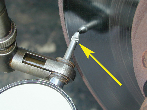
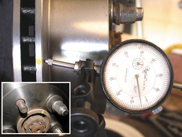
3. Mount dial indicator as shown in Figure 17. Indicator tip should be positioned at a small angle in reference to the rotor’s face. The indicator tip should point slightly up or down to prevent vibration as the rotor is turned.
4. (This step is optional.) Rotate the rotor in the direction the dial indicator tip is pointing until the lowest reading is obtained. With the indicator in this position, rotate the indicator scale until the zero is aligned with the needle.
5. Rotate the rotor 360º while watching the needle. If possible, use a ratchet and socket to rotate the hub/rotor assembly by the drive shaft axle nut. This allows a smooth full rotation and will result in a more accurate reading.
6. Note the rotor runout. The runout is the difference between the lowest number and highest number. Each mark on the dial face is equal to .001”. See Figure 18.
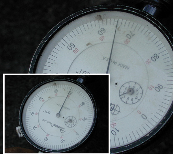
If step 4 was used, it is the highest number seen during the 360 degree rotation. Compare this number to the vehicle’s TIR (Total indicated runout) specification. If it is equal to or less than the specification, proceed with the rest of the brake job. If it is in excess of the allowable specification, indexing must be performed.
7. Rotate the rotor until the needle reads the highest number. Place a mark on the outside edge of the rotor at the position where the indicator tip is located. This represents the rotor high spot.
Place another mark on the hub at the same position. This represents the hub high spot. See Figure 19. Index the rotor to the hub by marking a wheel stud and rotor hat.
8. Remove the rotor and check the hub face and rotor mating surface for anything that would effect runout. If clean, rotate the rotor clockwise two stud holes and re-install the rotor using the same procedure in step 2.
9. Repeat steps 5 & 6. If runout is now within specifications, proceed with the rest of the brake job. If the runout is still outside of specifications, go to step 10.
10. Rotate the rotor until the needle is at the highest number. Check the position of the marks placed on the rotor’s edge and the hub to see if either one lines up with where the indicator tip is located. If the runout is in the rotor, the indicator tip should be closely aligned with the mark on the rotor’s edge. If this is case, the rotor is the source of the runout and will have to be machined or replaced based on thickness. If the indicator tip is aligned with the mark on the hub, the hub face has runout or has not been cleaned properly. If the hub face has runout, the hub will either have to be replaced or an on-the-car lathe will to be used to machine the rotor true to the hub.
The last step in the process involves the installation of the tire/wheel assembly. While in most technicians’ eyes this step is a “no brainer,” it can make or break the quality of the brake job in terms of runout. If the lug nuts are tightened in the proper sequence and to the correct torque, runout can be induced. The process of installing a wheel involves two key steps which, when done properly, will eliminate wheel induced runout. The steps are:
1. Tightening sequence; and
2. Step torquing.
Wheel Tightening Procedures
Proper tightening of the wheel lugs is necessary to promote safety and proper brake operation. All wheels are to be tightened using either a hand torque wrench or torque limiting socket following the procedure below:
1. Hand tighten all five lug nuts using star pattern.
2. Tighten all five lug nuts to approximately half specification using the star pattern.
3. Tighten all five lug nuts to full specification using the star pattern.
Note: If the wheel is not a five lug wheel, use the proper tightening pattern listed on the torque socket chart.
Note: On alloy and aluminum wheels it is advisable to re-torque the wheels after a short test drive.
Note: Never use lubricants or penetrating fluids on wheel studs, nuts or mounting surfaces. Wheel nuts, studs and mounting surfaces must be clean and dry. If penetrating fluid is used to remove the wheel lugs, clean the studs and nuts before re-installing. A thin layer of moly-lube may be used on the inner mating surface of the rotor where it meets the hub to slow down corrosion.
CALIBRATING YOUR IMPACT WRENCH
WARNING: Wear safety goggles when using torque sockets.
Torque Sockets are calibrated to an impact of 250 lb.ft. with 90-100 psi of air inlet pressure. Since most impact wrenches vary from 100 lb.ft. to 600 lb.ft. with various air inlet pressures, it is necessary to perform a simple calibration so torque accuracy will be uniform with whichever torque socket is used.
Calibrate the impact wrench using the following instructions:
1. Tighten a wheel nut with a torque socket (for example, try 100 lb.ft. socket).
2. Test the torque setting of the wheel nut with a calibrated torque wrench (preferably a dial indicator type), by measuring the break away torque in the tightening direction.
3. If the torque of this wheel nut is more than 100 lb.ft., turn the impact wrench output down.
4. Repeat the above procedure until the wheel nut, torque socket and torque wrench are in synch —plus or minus 5 lb.ft. of the 100 lb.ft. torque socket. The impact wrench is now calibrated for any of the torque sockets.
5. Each time the torque sockets are used, remember to set the impact wrench to the proper setting.
6. As long as the air inlet pressure in not changed, this setting will always be set for the torque sockets.
On-the-Car Lathes
You may have noticed I did not mention using an on-the-car lathe yet. I wanted to set the stage before I brought these into the equation. As you know, on-the-car lathes are designed to machine the rotor true to the hub. What would that gain us in what we have discussed so far? How about these:
• The hub and rotor mating surface should still be cleaned, but the cleanliness becomes less of an issue. The on-the-car lathe will compensate for small problems in this area;
• Hub runout is not a common occurrence but it would be a non-issue when using an on-the-car brake lathe; and
• Measuring installed runout and indexing rotor to hub becomes a non-issue as well.
The only thing left to do is tighten the wheel correctly. If you have an on-car lathe, you might consider using it more and if you don’t have one, you might consider looking at one. I will offer one piece of advice in this area. Look for an on-the-car lathe thats features include quick setup, easy, consistent compensation, one pass capability, built in non-directional finishing and durability.
Non-Runout Related Factors
Look closely at Figures 20 & 21.
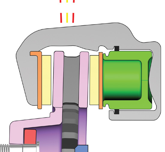
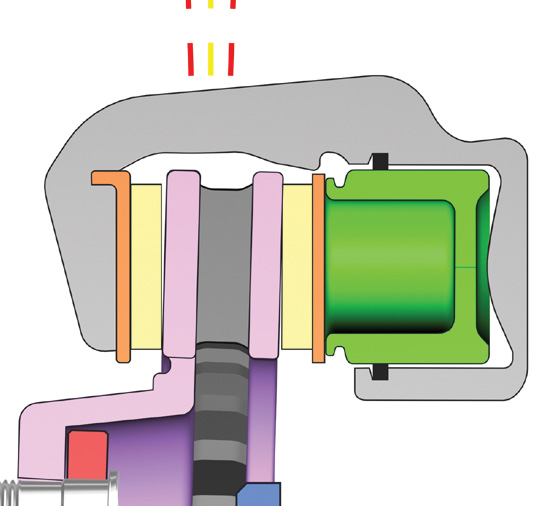
Both rotors shown have the same runout, but what they don’t have is the same gap between the pads and rotor. The gap between the pads and rotors in Figure 21 is much smaller than that of Figure 20. The smaller the gap, the more sensitive the vehicle will be to runout induced DTV. Remember, the wear of the high and low spots occurs during both brake apply and release. If something in the caliper assembly is preventing a full or complete release of either the outboard or inboard pad, that wheel will be more susceptible to this problem. Improper release of either pad could make even those rotors at or below .002” prone to this problem.
Effective inboard pad release will be effected by two types of conditions. The first of these involves how well the piston releases. A piston that does not return as far as it should reduces the gap between the inboard pad and rotor. Mileage, brake fluid condition and dust boot seal integrity all can impact the piston’s ability to release properly.
The second condition that can effect the release of the inboard pad involves how easy the pad can move in relationship to the caliper mounting bracket, knuckle or slide rails. If the inboard pad binds, complete release will not take place.
Outboard pad release can be impacted by two categories of failures as well. The most common of these is the slide hardware. If the caliper housing is not free to move on its mounting hardware, the outboard pad release will be effected.
The other category is the same as for inboard pad release, that is anything causing the outboard pad to bind where it contacts the bracket, knuckle or slide rails.
Nothing new about what impacts inboard or outboard pad wear, but understanding its influence on the issue of runout induced DTV is a fairly new concept. The moral of the story is short cutting quality brake work impacts more than just pad life.
The old “pad slap” has more chances to come back and haunt you than what you might have considered. Remember, just because the caliper applies and releases doesn’t guarantee it’s doing it as effectively as it should.