 By Omar Trinidad, assistant professor, Southern Illinois University
…Turn the ignition switch to the ON position. Test voltage at terminal 2 of connector C302.
Is the voltage 4.92V or higher?
If yes, go to step 4. If no, check for bad connections…
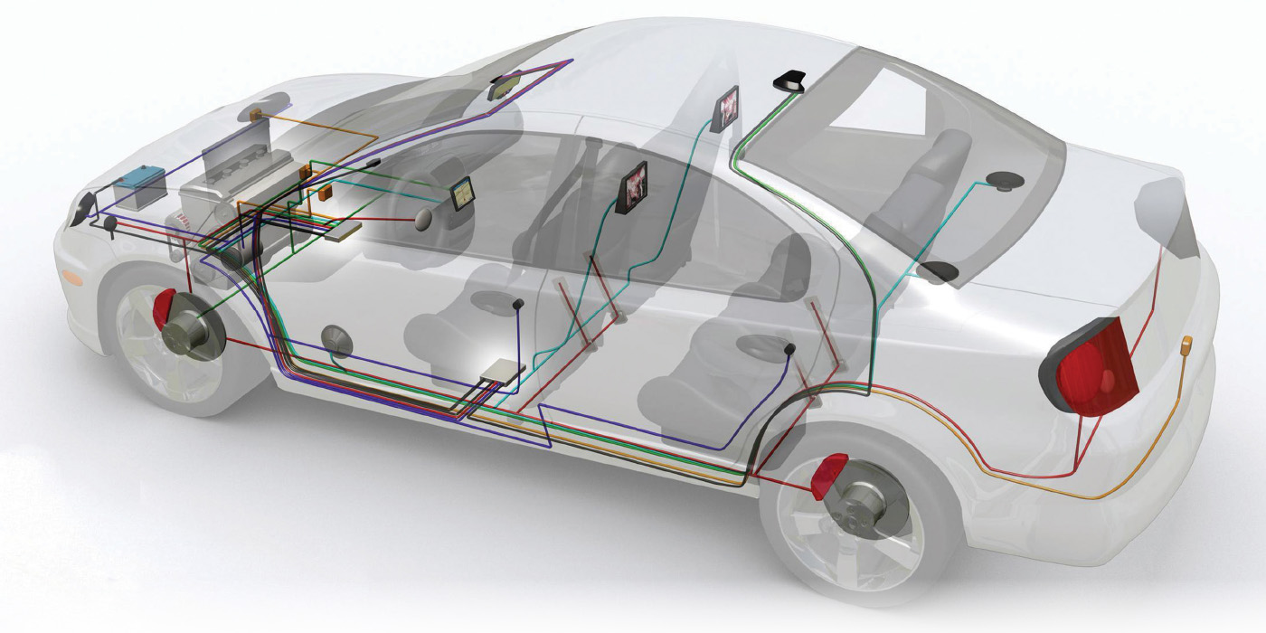
With the complexity of automotive electrical systems increasing steadily, manufacturers have developed troubleshooting trees and strategies (see example above) to make it easier for technicians to diagnose problems.
These steps and strategies are very helpful for technicians when followed, but they can also prevent them from using their cognitive skills. 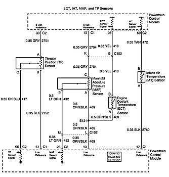
Therefore, it’s very important for technicians to understand how sensor circuits are designed, how the module interprets the signal voltage, and the criteria that trigger the module to set diagnostic trouble codes (DTC).
This article will help explain how switch inputs and variable resistive-type sensor circuits are designed, and provide simple electrical diagnostic tips.
What Lies Beneath
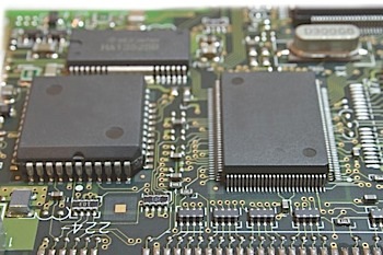
When looking at a wiring schematic, it’s tempting to wonder what lies within the box representing a control module.
The fact is, these thoughts usually arise when the technician is already frustrated at a vehicle in his bay.
Although it’s interesting to know what lies within the depths of a module, the most important parts to understand are the pull-up (PU) and pull-down (PD) resistors.
See Figure 1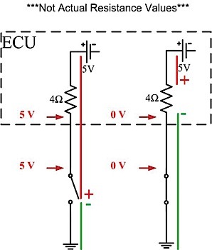
Understanding these two components and applying basic electrical principles will explain how most sensor circuits are designed.
The most important point to remember is that switch inputs or variable resistive-type sensors do not produce their own voltage, they merely control or change the voltage measured by the module.
All modules — including the power control module (PCM), transmission control module (TCM) and body control module (BCM) — utilize the same input circuit design.
These resistors are also used for monitoring outputs and other sensors, but this article will focus on switch inputs and variable resistive-type sensors.
Basic Principles
Pull-up and pull-down resistors are utilized for many electronic purposes, but they’re mainly used to allow signal voltage to change based on resistance changes in the sensor or switch, and enable the module to recognize circuit faults based on that signal voltage.
 These resistors are inside the module and are in series with each switch input or variable resistive sensor.
The module measures the voltage between the two resistors, or between the resistor and the switch, to infer the status (resistance) of the sensor or switch.
Without these resistors the voltage before and after the sensor would never change regardless of any resistance changes in the sensor.
In order to understand how these sensor circuits function, it’s important to understand two basic electrical principles.
First, positive and negative voltage/electrical pressure will build up at the highest resistance.
Last, if two resistors are wired in series, the resistor with the highest resistance will drop or build up the most voltage/electrical pressure. 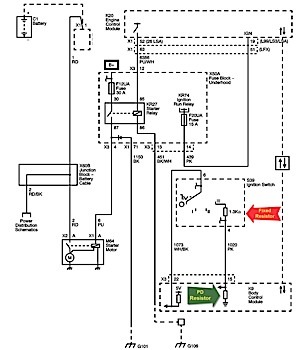
Switch Input Circuits
Figure 2 illustrates one switch in the ON/closed position and the other in the OFF/open position.
This particular circuit is designed to allow the module and the technician to measure 0 volts when the switch is closed and 5 volts when the switch is open.
Switch inputs such as a brake, door or window switch utilize the first electrical principle.
Due to the fact that the switch would be the highest resistance when the switch is open, the positive voltage and negative voltage will meet at the switch.
This explains why a technician and the module would measure 5 volts at the sensing side of the switch.
On the contrary, a technician’s meter would read 0 volts when the switch is closed because the positive and negative potentials would meet at the 4Ω resistor, which is the highest and only resistor in the circuit. 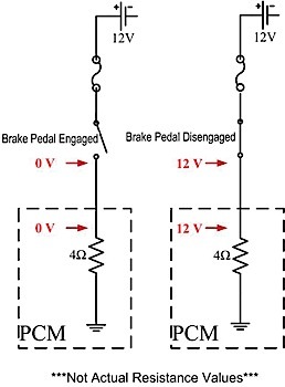
The meter won’t see a difference in potential between the two leads and will indicate 0 volts if the switch is closed with one DVOM lead on a chassis or battery ground and the other lead on the switch sensing side.
Notice that this example uses a ground-controlled circuit with a 5-volt reference. Some circuits, similar to one that will be discussed later, use a power-controlled 12-volt circuit.
Variable Resistive Input Circuits
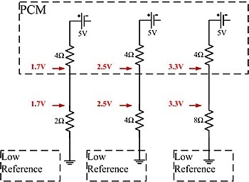
Using the second electrical principle listed above, Figure 3 illustrates the fact that the resistance of the second resistor affects the voltage reading before it.
A higher resistance would build up more voltage/electrical pressure before it, and the opposite result would occur if the resistance decreased.
This type of circuit is utilized in variable resistive-type sensors such as the engine coolant temperature sensor (ECT), throttle position sensor (TPS) and ambient light sensor (ALS).
Differing from a conventional conductor, the ECT is constructed of a semi-conductive material that decreases in resistance as temperature increases. 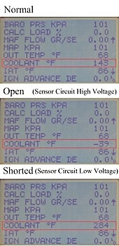
This explains why the signal voltage to the PCM decreases as temperature increases.
An increase in temperature will cause the ECT to decrease in resistance, thus building up less voltage/electrical pressure between the PU resistor and ECT.
The PCM is programmed to interpret the signal voltage as an indication of engine coolant temperature. From this information, the PCM can initiate closed loop, enable monitors and perform other emissions-related functions.
Conventionally, a contact-type ignition switch directs high current to most of the electrical system.
But with the implementation of push-start, advanced anti-theft and other body control functions, the ignition switch is now merely an input to a module rather than a high current switch.
Even non-push-start systems with conventional lock-cylinders and keys can utilize this design.
These systems have a specific fixed resistor for each key position. Figure 4 illustrates a 1.3K Ω inside the ignition switch in series with a PD resistor inside the BCM.
The BCM will reference the ignition switch position based on the voltage between the two resistors. Once the BCM informs the ECM that the key is in the start position and the shifter is in park or neutral, the ECM will send positive voltage to the control side of the starter relay. 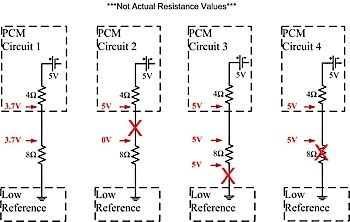
Diagnostic Trouble Codes
Understanding basic electrical principles and sensor circuits will allow any technician to efficiently diagnose any complex computer-controlled system.
However, due to the current compact design of connectors and wires, it’s now very difficult to acquire any voltage measurements at a connector through probe-type tools such as a t-pin. Fortunately, using a scan tool, DVOM and a jumper wire kit can alleviate this problem.
It’s always wise to start the diagnostic procedure by verifying the customer complaint and checking for DTCs. However, technicians must first understand how DTCs are set and interpret what voltages the module should and is currently seeing.
Furthermore, the technician must analyze the circuit to verify if it utilizes a PU or PD resistor.
 The resistors will always be on the signal side of the module, not the 5-volt reference or low-reference side of the sensor. Variable resistive-type sensors with a low-reference wire will utilize a PU resistor on the sensing side. On the other hand, sensors with a 5-volt reference wire, will utilize a PD resistor on the sensing side.
Diagnosing Switch Inputs
All DTCs are set by certain malfunction conditions. Input switches, such as a brake pedal switch, normally experience the lowest and highest voltage parameters (0 or source voltage). Most input switches can set two DTCs: switch circuit low input (voltage) or switch circuit high input (voltage). In addition, the module utilizes a systematic logic to set a DTC when certain conditions are met.
 For example, the brake pedal should never be engaged for a long period of time while the vehicle is accelerating. A P0719 brake switch circuit low input would be set if the PCM sees 0 volts at the brake switch input for a certain period of time while accelerating. This logic is programmed into the module.
The schematic on Figure 5 illustrates a basic brake switch circuit that can be categorized into three sections: the components before the switch, after the switch and the switch itself. Normally, 12 volts should be found at the PCM when the brake pedal is disengaged.
If 0 volts is found at the brake switch, there might be an open before it, or a blown fuse caused by a short to ground in between the PCM and the fuse. If the fuse is good, the next step would be to diagnose where the open is located.
A technician can test the resistance of each component or wire to find the open, but that would take some time to find every component or connector. It would be more efficient to test at the switch. After testing the resistance of the switch, a voltmeter can be used to verify the section containing the open.
 Depending on the source of voltage, the voltage before the switch should be high. If so, then the open is between the switch and the module. The PCM should only be suspected once all three sections are verified.
Diagnosing Variable Resistive-Type Sensors
As stated above, it is normal for a module to measure or sense the highest and lowest voltage threshold for switch inputs. However, unlike switch inputs, variable resistive-type sensors will set a DTC if the module senses the highest or lowest voltage threshold within a certain period of time (see Figure 6).
Sensor circuit high-voltage codes, such as a P0118 on an ECT sensor, will set if the PCM senses an output voltage of 4.92 volts or more for at least 2 seconds.
This fault will also cause the scan tool to indicate an extremely cold temperature. In contrast, sensor circuit low-voltage codes, such as a P0117 on an ECT sensor, will set if the PCM senses an output voltage of 0.08 volts or less for at least 2 seconds. 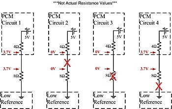
With a sensor circuit low-voltage code, the scan tool will indicate an extremely hot temperature.
There are also conditional-type codes that can be set, such as a P0128 cooling system malfunction. These conditional-type codes are set when the computer senses something illogical happening.
The PCM is programmed to infer that the coolant temperature should increase after a certain amount of engine running time. Utilizing the IAT sensor and other driving conditions, the PCM obtains an estimated engine coolant temperature. The cooling system malfunction code is set if the actual and estimated coolant temperatures are too far apart or if the actual temperature is lower than the estimated temperature reading.
This problem can be caused by a stuck-open thermostat, sensor circuit fault or a defective ECT.
As designed, the ECT will increase in resistance as coolant temperature decreases. The increase of resistance will increase the voltage/electrical pressure built up before it. With this stated, only an open or an extremely high resistance can cause the PCM to sense 4.92 volts or more and cause the scan tool to indicate an extremely low coolant temperature reading (see Figure 7).
Although a DVOM can be used to diagnose opens and high resistances in the circuit, it’s more efficient to utilize the scan tool and jumper terminals. Similar to the switch circuit diagnostic procedures, it’s important to categorize the sensor circuit into three sections: the wire before and after the sensor, and the sensor itself.
There are four steps to isolate an open or high resistance on sensor circuits similar to the ECT:
1. Unplug the sensor connector and test the resistance of the sensor. This also allows the technician to isolate the sensor, wires and the PCM. The sensor should be replaced if the resistance is overload (OL) or out of specification.
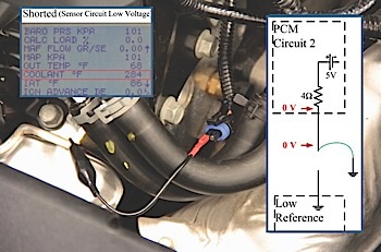
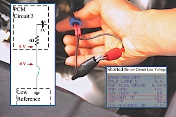
2. Use a terminal jumper lead to short the sensing wire to ground (see Figure 8).
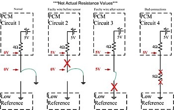
Due to the negative voltage on the sensing wire, the PCM should sense a voltage less than 0.08 volts and the scan tool will indicate an extremely hot temperature reading. If the scan tool does not indicate an extremely hot temperature reading, the fault is between the sensor and the PCM, see Figure 9 (circuit 2).
3. If the scan tool indicated an extremely hot temperature reading with the shorted sensing wire, the next step would be to jump the sensing and low-reference wires together (see Figure 10).
Similar to grounding the sensing wire, the voltage should stay low and the scan tool should indicate an extremely hot temperature reading. But, if the scan tool reading stays extremely cold, the fault is in the low-reference side of the circuit, Figure 9 (circuit 3).
4. Once the sensor and wires are confirmed, the only parts that could cause the fault are the terminal connections to the sensor or the PCM, Figure 9 (circuit 4).
One of the most misunderstood and often the first to be stated fault is a short. A short to power on the sensing wire will cause a sensor circuit voltage high DTC, and a short to power on the low-reference side will melt the wire or destroy the module.
 On the other hand, only a short to ground on the sensing wire or an internally shorted sensor will trigger a sensor circuit voltage low DTC (see Figure 11). Both of these faults can be tested with an ohmmeter. A technician can measure the resistance of the sensor to verify that the sensor is within specifications.
But if a short to ground is suspected, the technician should disconnect the sensor and PCM connectors, insert a jumper terminal in the sensing wire connector terminal and test for resistance/continuity to ground. The ohmmeter should read OL. Again, it’s crucial that the PCM should only be suspected after all of the three sections have been thoroughly tested.
A technician doesn’t need to know everything about the internals of a module. However, it’s very important for all technicians to understand how the sensor circuit is designed, the normal voltage range of the sensor and the enabling conditions of any DTCs they are diagnosing.