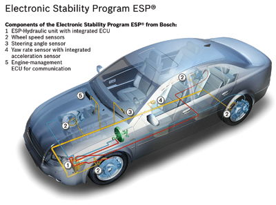
Measuring the steering wheel position angle and rate of turn, which are critical for Electronic Stability Control (ESC) systems, is the job of the Steering Angle Sensor (SAS). The scan tool will typically display the information in degrees.
The SAS is typically a part of a sensor cluster in the steering column. The sensor cluster will always have more than one steering position sensor, some sensor clusters have three sensors for redundancy and to confirm the data. It is important for the ABS/ESC module to receive two signals to confirm the steering wheel’s position. These signals are often out of phase with each other.
ANALOG STEERING ANGLE SENSORS
Analog SASs are similar to throttle positions sensors. SASs are wired with a 5-volt reference, chassis ground and signal output. To test the SAS, you have to back probe a connector that is typically under the steering column.
As the steering wheel is turned, the SAS produces a signal that toggles between 0 and 5 volts as the wheel is turned 360º. As the wheel is turned lock-to-lock, the voltage will reach 5 volts three times and 0 volts three times.
Often, other wires for the torque sensor for the electric power steering go to the SAS sensor cluster. With meters connected to the signal wires for the two SAS sensors and their commons connected to the ground, it is possible to observe the 0- to 5-volt signal and how the signals are out of phase for the sensors.
With the wheels straight ahead, one sensor reads 2.8 volts and the other .4 volts. If the voltages were the same, it could be a sign the signal wires were shorted together.
With the wheel turned fully to the right, the voltages do not match, which is perfectly normal.
On most vehicles turning to the right creates a positive voltage and to the left creates a negative voltage. But, some cars are opposite. The labscope pattern shows the signal traces from the two sensors on top of each other. This can be helpful when comparing the signals and if one is flat lining.
DIGITAL STEERING POSITION SENSOR
A digital SAS is often called a “contactless sensor.” This type of sensor uses LED light, a wheel that acts as a shutter and an optic sensor that measures interruption in the light, just like a distributor on a Chevy LE1 V8.
The signal for these types of sensors is a digital square-wave signal. The frequency of the voltage changes depending on the speed the wheel is turning.
The sensor clusters for these sensors often contain a third sensor just to measure if the wheel is centered. With the wheel straight, the voltage is close to 0 volts. When the steering wheel is moved off center, the voltage goes high.
CAN BUS MODULE STEERING ANGLE SENSORS
Some SAS clusters and sensor modules connect to a Controller Area Network (CAN) bus. The SAS module can connect directly to the ABS/ESC module on a CAN bus or it can be part of the overall CAN Network in a loop that connects various modules in the vehicle.
A CAN bus is a high-speed serial data network that communicates in binary language to other modules or nodes. When you connect your scan tool to a vehicle, it becomes a node on a network. High-speed CAN buses, like GM LAN, use only two wires per module or node to communicate vast amounts of data. This means that a node, like a SAS module, has to have the ability to interpret and create signals that can be understood by other modules on the bus.
TESTING DIRECT-TYPE CAN SAS SENSORS
The best way to test modules on a high-speed CAN bus is with a scan tool. Most tools are able to look at the data directly. But, some scan tools may not be able to look at the datastream directly for a SAS due to software issues with the tool.
If you are in this situation, it is possible to observe how the actuation of a sensor, switch or component can change activity on the bus.
All CAN bus modules have power and two high-speed CAN wires. One wire toggles the voltage between 1.5 and 2.5 volts and the other wire will toggle the voltages between 2.5 and 3.5 volts. Serial data buses toggle the voltages on the network to produce the 1’s and 0’s of binary language. This toggling of the voltages communicates information and commands.
If you connect your scope between chassis ground and the bus wires and look at voltage, it is possible to see packets of data being communicated on the bus.
On a direct-type SAS CAN sensor, you can see the sensors communicating with ABS/ESC module as the wheel is turned. It is impossible to tell what is being communicated, but it is possible to see they are communicating.
On some vehicles, the SAS sensor cluster is part of a module that may include switches for the turn signals, steering wheel audio controls and wipers. This module might have multiple CAN lines coming out of it. Often, the SAS cluster cannot be replaced on its own. It might require replacement of the entire unit.
RESETING STEERING ANGLE SENSORS
Many vehicles require the SAS be reset or recalibrated after an alignment is performed or parts in the steering system are replaced. There are three types of reset procedures. First, systems that self calibrate on their own. Second, vehicles that require specific wires or buttons be pressed. Third, systems that require recalibration with a scan tool.
Even if the SAS is out of calibration, most vehicles have ways of sensing if it is traveling in a straight line. If the angle is far enough out of range, it might set a trouble code and disable the ESC system.
SELF-CALIBRATION
On some Chrysler vehicles, recalibrating the sensor after an alignment or if the battery has died, is just a matter of turning the wheels lock to lock, center the wheel and cycle the key. This “auto learn” is becoming more common on newer vehicles.
SCAN TOOL STEERING ANGLE SENSOR RESET
There are many options for scan tools to reset SASs. Some tools are even integrated into an alignment system. But, most tools recommend that the calibration be performed on a level surface. Also, it is a good idea to perform a lock-to-lock turn to complete the calibration.
While performing the Zero Point Calibration on Toyota vehicles, do not tilt, move or shake the vehicle. The vehicle must remain in a stationary condition throughout the entire process. Be sure to perform the procedure on a level surface with an inclination of less than 1%.
1. If the vehicle is equipped with an A/T, ensure that the shift lever is in the “P” range and the parking brake is applied. If the vehicle is equipped with a M/T, ensure that the parking brake is applied.
2. Turn the ignition switch ON.
3. Using a jumper wire in terminals 4 and 12 of the DLC, repeat a cycle of short and open between terminals four times or more within eight seconds.
4. Verify that the VSC indicator light is lit indicating the recorded zero point is erased.
5. Turn the ignition switch OFF.
6. Be sure the jumper wire is disconnected.
7. Turn the ignition switch ON.
8. Check that the VSC warning light goes off about 15 seconds after the ignition switch is turned ON.
9. After ensuring that the VSC warning light remains OFF for two seconds, turn the ignition switch OFF.
10. Connect terminals 4 and 12 of DLC using SST 09843–18040.
11. Turn the ignition switch ON.
12. After turning the ignition switch ON, check that the VSC warning light is lit for about four seconds and then starts quick blinking at 0.13 second intervals.
13. After ensuring the blinking of the VSC warning light for two seconds, turn the ignition switch OFF.
14. Remove the SST from terminals 4 and 12 of DLC.
15. Drive the vehicle for at least 5 minutes to confirm Zero Point Calibration is complete.
If viewing the scan tool after the repair, the Steering Angle Sensor may remain at 1150 until the vehicle reaches 28 mph. This is a normal condition until the learned values of the steering angle have been achieved.