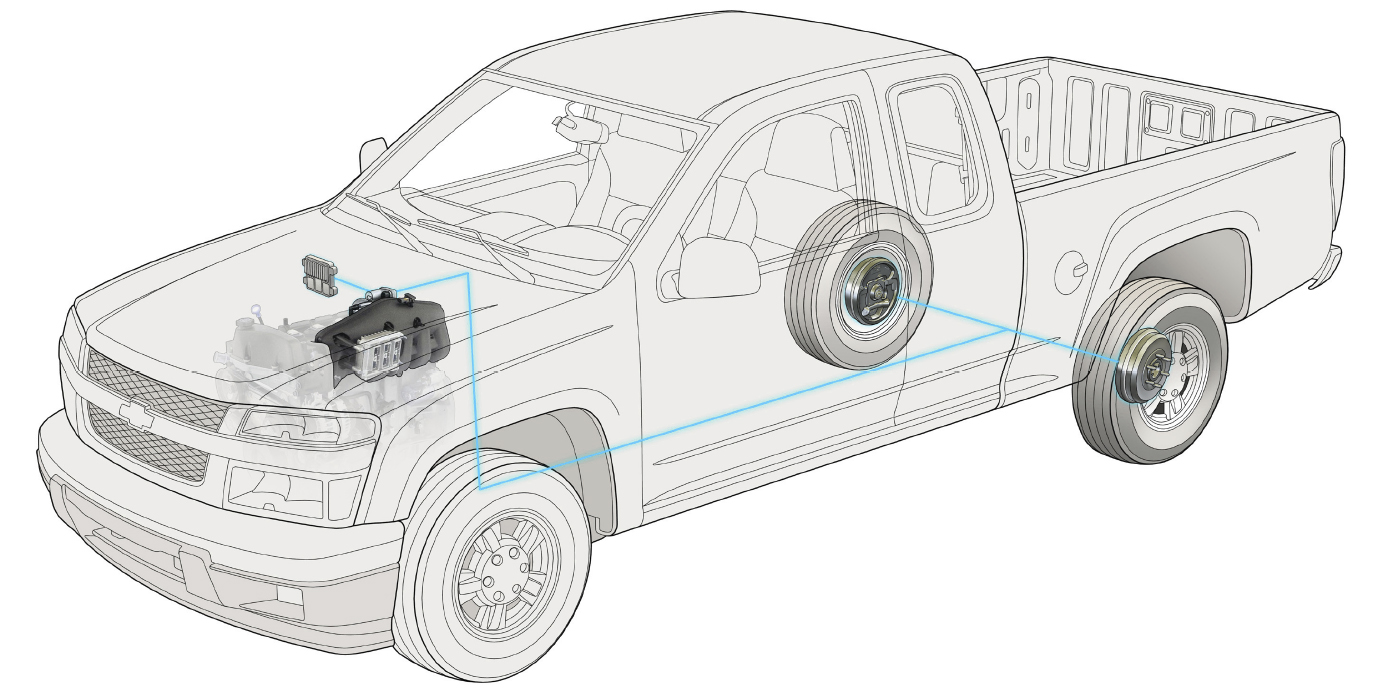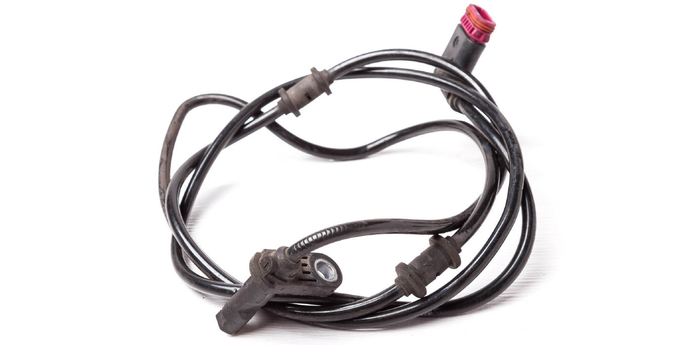
If you are replacing a wheel bearing on a late-model vehicle, you’ll be dealing with a wheel speed sensor. In the past decade, wheel speed sensors have been moving from differentials, axles and knuckles to inside or on the wheel bearing or hub unit. At this location, the sensors are more accurate and often more protected from the elements.
The average wheel-bearing job may require a scan tool, scope or meter to verify the operation of the sensor. Most vehicles today use two types of wheel speed sensors — variable reluctance (passive) and magnetoresistive (active).
 Variable Reluctance
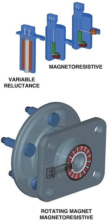
The variable-reluctance magnetic sensor has a permanent magnet pickup core and coil surrounding the magnet. These are typically found on pre-2003 vehicles. The sensor is mounted at a specific gap from a notch-and-tooth reluctor ring. These sensors are less accurate and might read 3-5 mph on a scan tool when the vehicle is sitting still.
The rotation of the reluctor ring increases and decreases the magnetic field between the notch and the tooth to generate voltage in the coil.
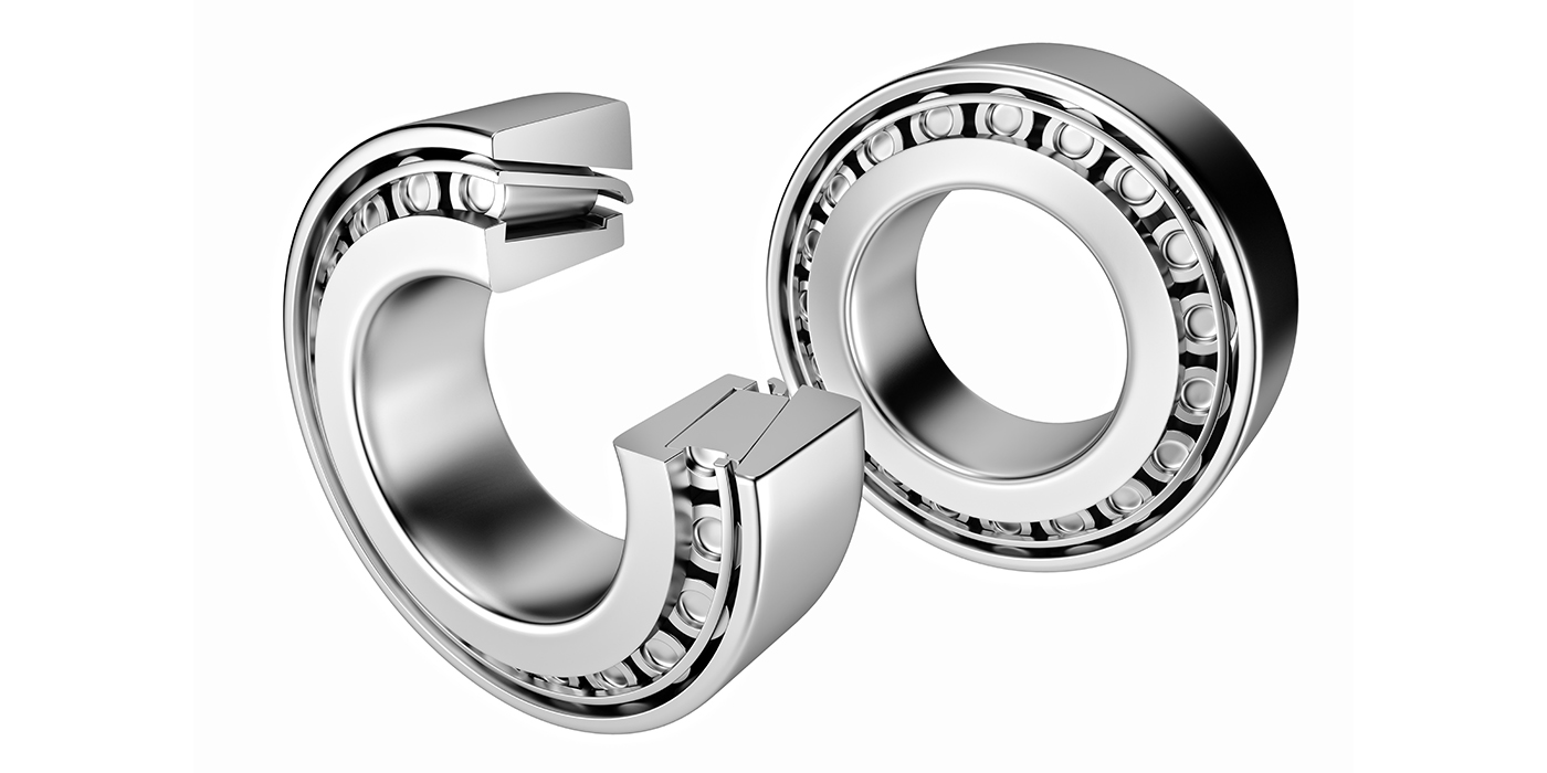
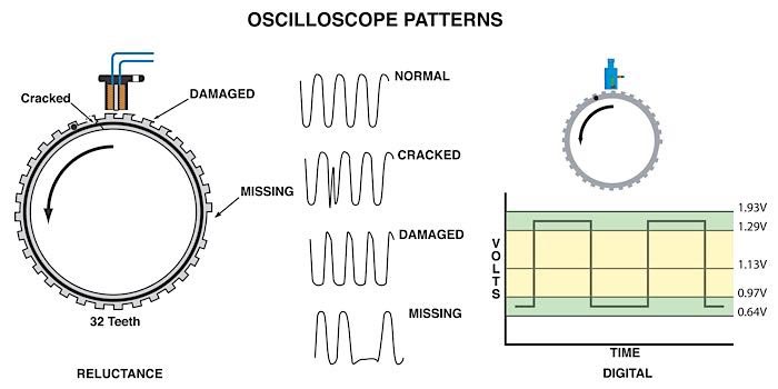
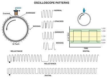
As the gap between the notch and the ring changes with the rotation of the reluctor, the sensor generates an analog sine wave voltage signal. The voltage signal will increase in amplitude with an increase in the speed of the reluctor ring. The change in amplitude can affect the switching toggle to the computer where a cracked reluctor ring may produce an extra switching toggle. The variable-reluctance sensor is a two-wire sensor in a hub unit between the bearing races.
Magnetoresistive
A magnetoresistive sensor has a sensing element that contains an output module mounted on a substrate and magnetic material. These magnetic rings are often located on the seal of the bearing. The magnetoresistive sensor’s main advantage is the ability to sense direction and operate with a wide air gap. The sensor is more stable in high-vibration conditions and operates more efficiently than the reluctance sensor.
The sensor can detect the direction of rotation of the reluctor ring and zero speed. The sensor’s compact size allows it to be incorporated into a hub bearing utilizing an alternating magnetic pole reluctor ring that is built into the rubber seal. A magnetoresistive sensor can be a two- or three-wire sensor. The three-wire sensor has a power, ground and signal connector pin.
The two-wire sensor has a power and signal connector pin. The ground is a part of the mounting for the sensor. The magnetoresistive wheel speed sensor power input can range from 12 to 15 volts from the ABS controller.
The sensor produces a square wave signal with a high signal of 1.93 volts and a low signal of 0.64 volts. The high signal must cross 1.29 volts, and the low signal must cross 0.97 volts. The main advantage is that the amplitude of the signal does not change.
Diagnostic Procedures
The diagnosis of a trouble code or problem condition requires an investment in information and tools, which are expensive and are a good reason to charge for diagnostics. Diagnosing a DTC or failure condition should start by conducting a Technical Service Bulletins (TSB) search from your information database. The condition may already exist and there could be a known fix that can save time and money.
Trouble Codes and Data
The scan tool is the most efficient tool for diagnosing ABS sensor problems. If you are servicing three- and four-year-old vehicles, your shop cannot function well without it. A digital volt meter (DVM) and oscilloscope are used to verify a DTC or problem. An oscilloscope is the ultimate DVM. It measures voltage and time, and many scan tools have a built-in scope. You can survive without a scope, but you must have a good DVM that can measure frequency. Frequency can provide information that a signal is present.
 Oscilloscope
The use of an oscilloscope can be a time-consuming process that requires a certain amount of information to accurately display a wheel speed sensor wave pattern.
The following contains information for setting up an oscilloscope. The average automotive tire ranges from 24 to 28 inches in outside diameter. At one revolution per second, the vehicle would be traveling at a speed of 4-5 mph.
The frequency of the sensor would give you an estimate of the number of teeth on the reluctor. This information will help you set the time base for your scope. The time base is set to allow all of the signals per revolution to appear on the display. If a wheel rotates at one revolution per second, the sensor and tone ring produces a 32 hertz frequency signal, and the time base is calculated by dividing the frequency by one.
This would be 0.03125 seconds, or 30 milliseconds (ms) rounded down to the nearest millisecond. Set the time base for 30 ms to 40 ms. The amplitude of the signal for a inductive sensor will change as the speed of the reluctor increases. This will also affect the oscilloscope display.
A low amplitude signal can indicate an air gap or high-resistance connector condition. If the oscilloscope you are using has a feature that will allow you to capture a series of frames, you can examine the trace of one revolution of the reluctor. A cracked, damaged or missing reluctor can produce a signal that may not be processed by the BCM. The square wave signal does not need to be processed by the BCM; it is a direct input. Trouble codes C1141 through C1144 can be caused by a missing tooth and can be verified with a scope.
The aftermarket technician has to be more proficient in diagnosing system failures. The scan tool and service information are the primary resources you need, but a thorough knowledge of fundamental mechanical and electronic component operation is also important for finding the right fix the first time.