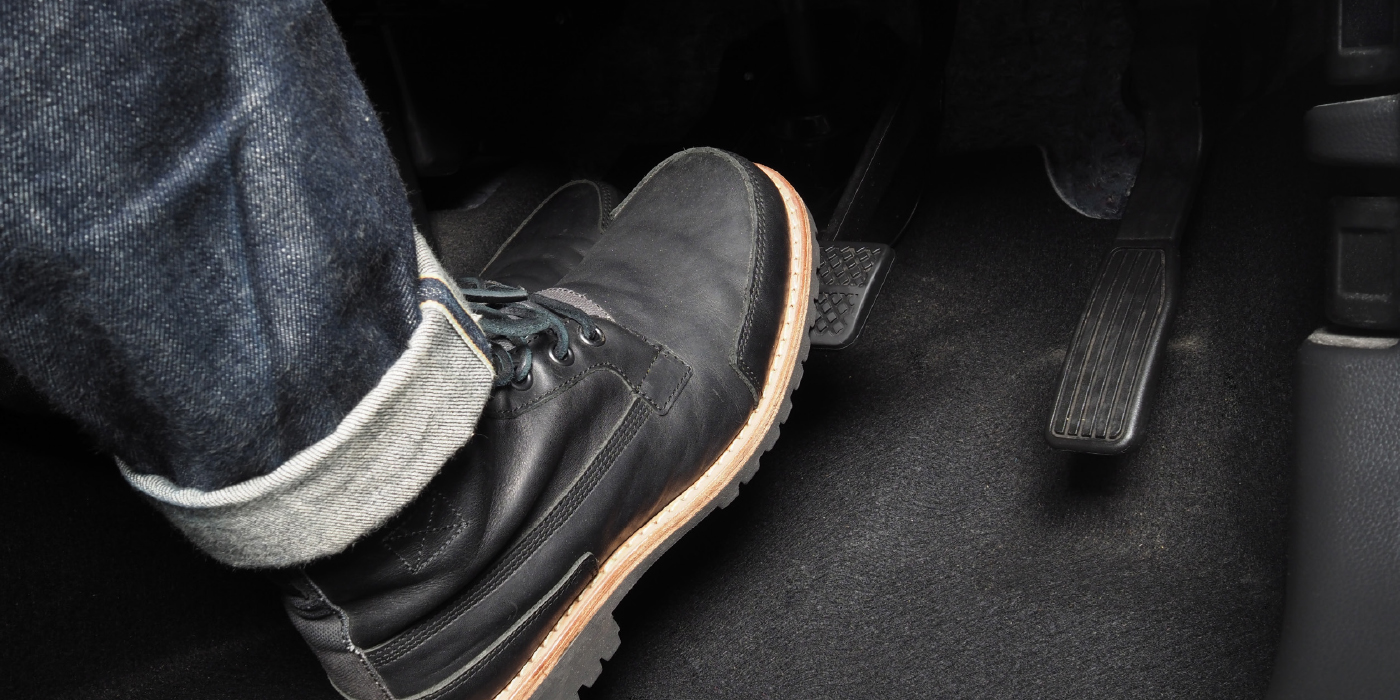
Let’s say a vehicle had .003” of lateral runout when measured at the outside face of the rotor. If this vehicle is riding on 205/55R16 tires, in one mile, the high-spot with .003” of runout goes past the caliper approximately 836 times. Over 6,000 miles, that spot on the rotor will go past the pads more than 5 million times. Every time this spot passes the pads, a little bit of the rotor’s material is removed. Over the course of those 5 million revolutions, enough material is removed to create a thickness variation that can be felt by the driver.
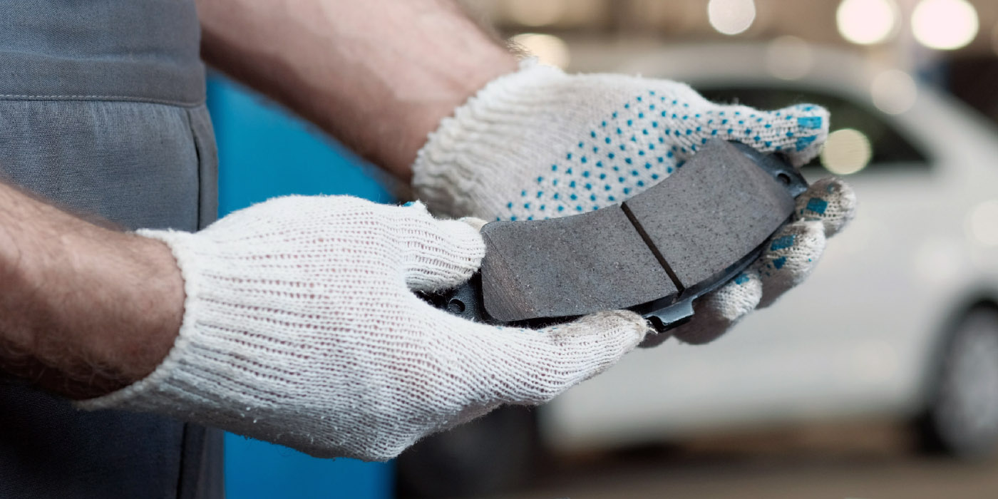
This is why it is critical to measure thickness and runout in a brake rotor and wheel flange even if new rotors are going to be installed.
Here are the recommended steps for measuring thickness and runout. These are the bare minimum steps you should be following for old and new rotors.
Before Starting
Mark the original position of the rotor with a paint or grease marker before removing the rotor.
Rotor Thickness
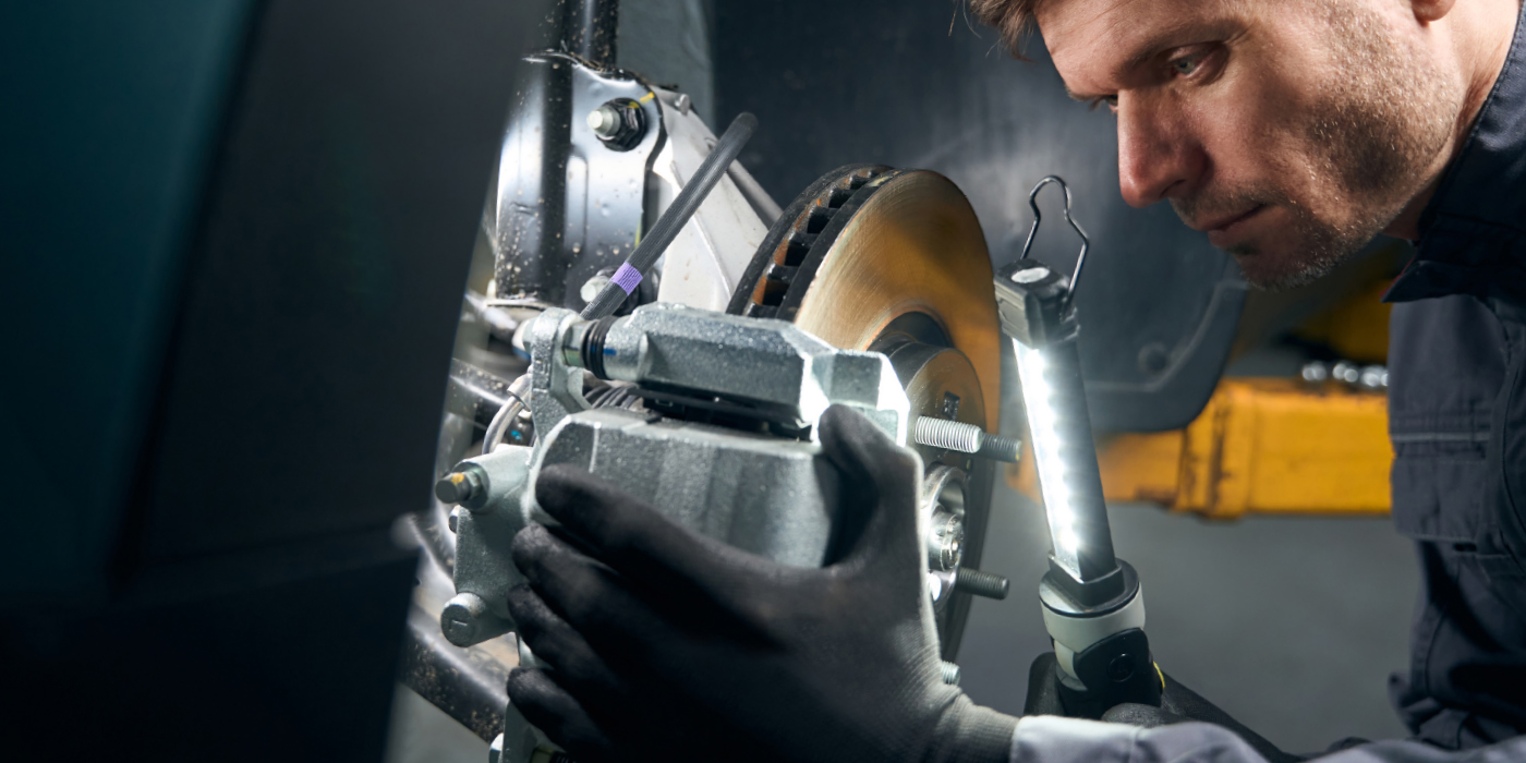
1. Inspect the rotor’s surface for defect, corrosion or cracks.
2. Find the discard measurements on the rotor. On some aftermarket rotors, they will be laser-etched into the sides of the plates. If a discard measurement can’t be found, look it up along with the specification for thickness variation or parallelism.
3. Using a micrometer, measure the thickness of the rotor in at least six spots that are opposite from each other.
4. Record the results. Variations in thickness should be between .001” and .003”.
Rotor Runout Measurement
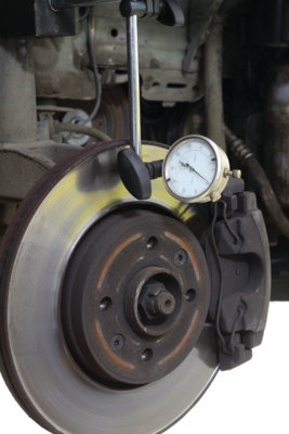
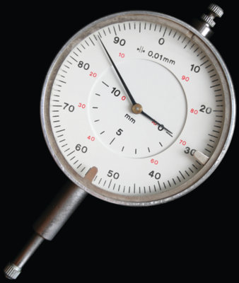
1. Mount the dial indicator to a rigidly secure portion of the suspension, like the knuckle. Do not mount the arm to tie-rod ends or control arms. Position the indicator tip perpendicular to the rotor’s surface and 0.5” from the edge of the rotor.
2. Tighten down the rotor with the correct conical washers to the recommended lugnut specification.
3. Set the dial to zero and turn the rotor.
4. Mark the high and low spots of the runout. For most cars, the specification will be .002” or less.
5. Remove the rotor. Inspect the mounting surface inside the hat. Remove any corrosion or debris.
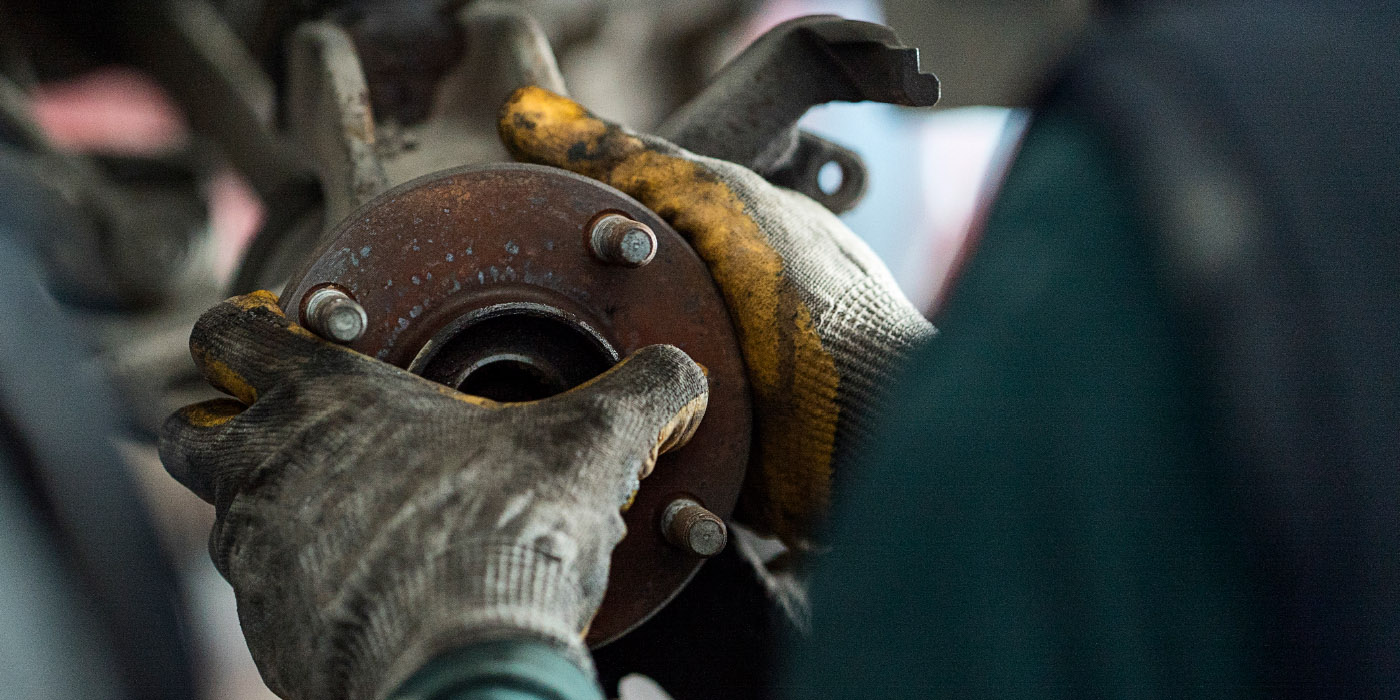
Runout in the Wheel Flange
1. Rotate the hub bearing assembly by hand. Any roughness, play or noise from the bearing is an indication of damage. Verify that the condition is normal or requires replacement.
2. The dial indicator base should be placed or clamped rigidly on a secure portion of the suspension. Position the indicator tip as perpendicular on the wheel flange as possible.
3. Set the dial indicator to zero. Next, turn the flange at least twice and observe the high and low spots of runout.
4. Mark the high and low spots of runout on the flange.
5. If the flange has more that .002”, or the readings are inconsistent, further corrective actions might need to be taken after rotor runout is measured.
Matching the Hub to the Rotor
By measuring and marking the high and low spots of runout in the hub and rotor, it is possible to match the high spot of runout in the hub with the low spot of runout in the rotor. This technique can be used to minimize the amount of material removed with an on-the-car brake lathe.
Flange runout can be corrected with tapered shims that are available to correct a runout of 0.003” (0.075 mm) to 0.009” (0.230 mm). A runout of more than 0.005”(0.125 mm) at the bearing flange cannot be corrected by the use of a shim. The combination of the rotor and bearing flange could prevent the rotor from being turned. Check the bearing flange runout after friction surface runout. Check flange runout by changing the rotor position 180º on the bearing. If the high spot changes 180º, the rotor could be OK or ready to turn after the bearing is shimmed.
Components should be marked as you perform an inspection of the assembly. Check the bearing endplay. Mark the relation of the rotor to the bearing flange. Mark the rotor high and low runout spots on the rotor friction surface. The low spot marked as zero and the high spot as 0.XX”. Mark the high and low runout spots on the bearing flange with the same method as the rotor friction surface.
Once you have collected the data, the following comparisons should be made:
• If the endplay exceeds manufacturer’s specifications, replace the bearing and recheck runout.
• Compare bearing flange to rotor runout position.
• If the shim cannot correct the runout, the bearing should be replaced.
• Check the rotor thickness. The minimum dimension should be stamped or cast into the rotor. There has to be enough thickness to cover the runout without going below the minimum thickness.
On-the-Car Runout Minimization
Today, you can purchase an on-the-car brake lathe that, after it has been attached to the vehicle, will automatically compensate for runout — quick and easy.
In some cases with excessive runout, a new rotor should be machined to match the vehicle, which helps to match the rotors to the hub flange.
Using an on-the-car lathe can help to reduce runout on new rotors. The main advantage of these lathes is that they are able to cut a rotor in its operating plane. This means that the rotor is machined to match the hub.
It has often been said that you should never machine new rotors, but what if the runout exceeds the manufacturer’s specifications when the new rotor is installed on the vehicle? This situation makes it permissible to machine a new rotor with an on-the-car brake lathe.