Some 2004-’06 RX 330 owners may experience a moan noise heard at 1,100 rpm to 1,400 rpm with the A/C on.
Applicable Vehicles: 2004-’06 model year RX 330 vehicles.
Repair Procedure:
1. Verify the customer concern.
a. Start the engine.
b. Turn on the A/C.
c. Hold the engine rpm between 1,100-1,400.
d. Turn off the A/C.
If there is a noticeable moan sound with the A/C on and no sound when the A/C is off, continue with this repair procedure.
2. Remove the engine side cover: Remove the four clips and then remove the engine side cover.
3. Evacuate the refrigerant HFC-134a (R-134a) with an R-134a Refrigerant Recovery/Recycling Machine.
4. Remove the engine under-cover assembly. Remove the five clips, four bolts and two screws, and then remove the engine under cover. 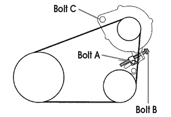
5. Remove V belt No. 1 (from the cooler compressor to crankshaft pulley). See Fig. 1.
a. Loosen bolt C.
b. Loosen bolt A.
c. Loosen bolt B and remove V belt No. 1 (from the cooler compressor to crankshaft pulley).
6. Disconnect cooler refrigerant discharge hose No. 1.
a. Remove the nut and disconnect cooler refrigerant discharge hose No. 1 from the compressor and magnetic clutch.
b. Remove the O-ring from cooler refrigerant discharge hose No. 1.
Note: Seal the opening of the disconnected parts using vinyl tape to prevent moisture and foreign matter from entering.
7. Disconnect cooler refrigerant suction hose No. 1.
a. Remove the bolt and disconnect cooler refrigerant suction hose No. 1 from the compressor and magnetic clutch.
b. Remove the O-ring from cooler refrigerant suction hose No. 1.
Note: Seal the opening of the disconnected parts using vinyl tape to prevent moisture and foreign matter from entering.
8. Remove the compressor and magnetic clutch.
a. Remove the bolt and wire harness bracket.
b. Disconnect the connector and clamp.
c. Remove the two bolts, nut and the cooler compressor bracket.
d. Remove the three bolts, the compressor and the magnetic clutch.
9. Remove the magnetic clutch assembly. 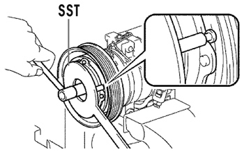
Note: Do not change the combination of the magnetic clutch washers used before disassembly.
a. Remove the two bolts and bracket.
b. Place the compressor and magnetic clutch in a vise.
Note: Do not get the bracket and harness caught in the vise.
c. Using tool SST O7112-76060 (see Fig. 2), hold the magnetic clutch hub.
d. Remove the bolt, magnetic clutch hub and magnetic clutch washer.
There is no set number of magnetic clutch washers since they are used for adjusting.
10. Install the magnetic clutch washers and new magnetic clutch hub. Using the SST, hold the magnetic clutch hub and torque the bolt. Torque: 18 Nm (13 ft.-lbf.)
Make sure that there is no foreign matter or oil on the compressor shaft, bolt and clutch hub.
11. Inspect the magnetic clutch clearance.
a. Set the dial gauge to the magnetic clutch hub.
b. Connect the positive (+) battery lead to terminal 3 of the magnetic clutch connector and the negative lead to the ground wire. Turn the magnetic clutch on and off and measure the clearance.
Standard clearance: 0.35 to 0.60 mm (0.013 to 0.023 in.)
If the measured value is not within the standard range, remove the magnetic clutch hub and adjust it with magnetic clutch washers. Note: Adjustment should be performed with three or fewer magnetic clutch washers.
c. Remove the compressor and the magnetic clutch from the vise.
d. Install the bracket with two bolts.
12. Remove cooler refrigerant discharge hose No. 1.
a. Remove the bolt and disconnect the cooler refrigerant discharge hose from the condenser assembly.
b. Remove the bolt from the piping clamp and remove the cooler discharge hose.
Note: The next step is for 2004 model year vehicles only. If the vehicle is a 2005-’06 model year, go to step 14.
13. Replace the cooler bracket.
a. Remove the bolt and then remove the cooler bracket.
b. Install the new cooler bracket and hand-start the bolt.
c. Torque the bolt. Torque: 9.8 Nm (85 in.-lbf.).
14. Install new cooler refrigerant discharge hose No. 1. 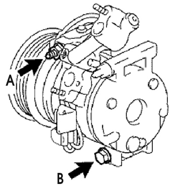
a. Sufficiently apply compressor oil to the O-ring and fitting surface of the condenser.
b. Connect the cooler refrigerant discharge hose to the condenser assembly and hand-start the bolt.
c. Torque the bolt. Torque: 9.8 Nm (85 in.-lbf.)
d. Place the piping clamp on the isolator stud and hand-start the nut.
e. Torque the nut. Torque: 9.8 Nm (85 in.-lbf.)
15. Install the compressor and magnetic clutch. 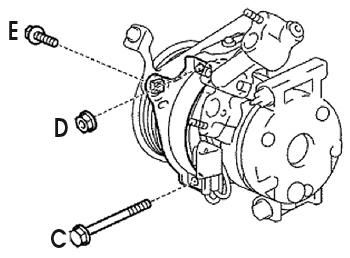
a. Hand-start the three bolts.
b. Fully tighten the compressor and magnetic clutch with bolt A and bolt B, Fig. 3. Torque: 25 Nm (18 in.-lbf.)
c. Install the cooler compressor bracket with the two bolts and nut, Fig. 4.
Bolt C – Torque: 25 Nm (18 in.-lbf.)
Nut D – Torque: 25 Nm (18 in.-lbf.)
Bolt E – Torque: 18 Nm (13 in.-lbf.)
d. Tighten the compressor and magnetic clutch with bolt F, Fig. 5. Torque: 25 Nm (18 in.-lbf.)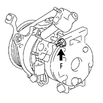
e. Connect the connector and clamp on the cooler compressor bracket.
f. Install the wire harness bracket with the bolt.
16. Install cooler refrigerant suction hose No. 1.
a. Remove the attached vinyl tape from the hose.
b. Sufficiently apply compressor oil (ND-01L8 or equivalent) to the new O-ring and fitting surface of the compressor and magnetic clutch.
c. Install the O-ring to cooler refrigerant suction hose No. 1.
d. Install cooler refrigerant suction hose No. 1 to the compressor and magnetic clutch with the bolt. Torque: 9.8 Nm (87 in.-lbf.)
17. Install cooler refrigerant discharge hose No. 1.
a. Sufficiently apply compressor oil to the new O-ring and fitting surface of the compressor and magnetic clutch.
b. Install cooler refrigerant discharge hose No. 1 to the compressor and magnetic clutch. Hand-start the nut. Torque: 9.8 Nm (87 in.-lbf.)
18. Temporarily install V belt No. 1 (from the cooler compressor to crankshaft pulley).
19. Adjust V belt No. 1. Apply drive belt tension by turning bolt B (see Fig. 1).
Drive Belt Tension: New Belt: 170 +/- 10 lbf.; Used Belt: 125 +/- 10 lbf. Note: “New belt” refers to a belt that has been used on a running engine at idle for five minutes or less. “Used belt” refers to a belt that has been used on a running engine at idle for five minutes or more.
Note: Check that the drive belt fits properly in the ribbed grooves.
20. Fully tighten V belt No. 1, Fig. 1 .
a. Tighten bolt A. Torque: 18 Nm 13 ft.-lbf.)
b. Tighten bolt C. Torque: 58 Nm (43 ft.-lbf.)
21. Recharge the refrigerant HFC-134a (R-134a). Specified amount: 600 +/- 50 g (21.15 +/- 1.76 oz.)
22. Warm up the engine.
23. Inspect for any refrigerant leakage.
24. Verify the repair.
a. Start the engine.
b. Turn on the A/C.
c. Hold the engine rpm between 1,100-1,400 and confirm no moan sound.
d. Turn off the A/C.
25. Install the engine under-cover assembly.
a. Install the engine under cover.
b. Install the five clips, four bolts and two screws.
26. Install the engine side cover.
a. Install the four clips.
Courtesy of Mitchell 1.