COMMON IGNITION SENSOR CONFIGURATIONS
Waste spark or “distributorless” ignitions began to replace distributor ignitions during the 1980s. All that the basic waste spark ignition needs for timing input is a crankshaft position sensor (CKP) to indicate when a pair of cylinders reaches TDC. In this basic system, the CKP provides a reference point for the PCM so it can advance or retard ignition timing according to engine speed and load.
To create the spark, the PCM incorporates a “coil driver” that “pulls” the primary circuit on the appropriate coil to ground. The coil then supplies a spark to one cylinder approaching TDC compression stroke and another cylinder approaching TDC exhaust stroke. The spark on the exhaust stroke cylinder is “wasted,” thus the term “waste spark” ignition.
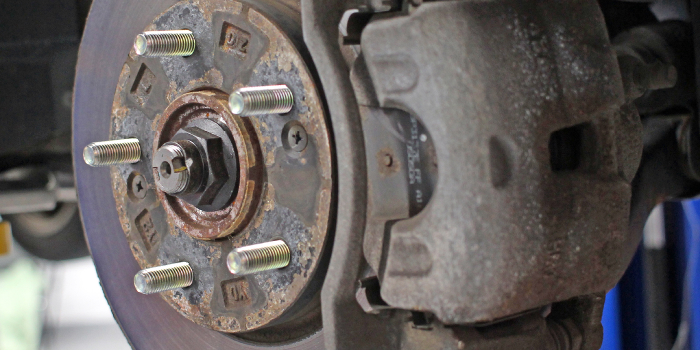
Engines using a basic waste spark ignition generally employ non-sequential or “banked” fuel injection configuration to supply fuel to the cylinders. Four- and six-cylinder engines are the most likely to incorporate banked fuel injection systems in which one-half of the fuel injectors are fired simultaneously. Ignition systems without a camshaft position sensor (CMP) generally time the fuel injection by switching injector timing 180° during cranking until the cranking speed increases and the engine starts. If the system incorporates a CMP, the CMP indicates when the #1 cylinder is reaching TDC. See Photo 1.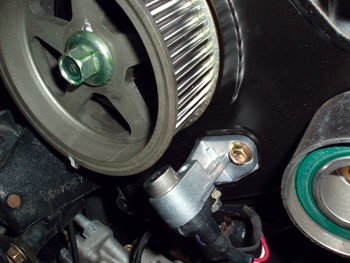
The waste spark ignition can also incorporate an ignition control module (ICM) that works in concert with the PCM. Waste spark systems with sequential fuel injection also incorporate a CMP to achieve the correct firing order. In most external ICM configurations, the CKP and CMP signals are routed through the ICM. The CKP signal is relayed to the PCM, where the PCM advances or retards the “spark out” timing signal, which is then sent back to the ICM where it is used to activate the ignition coil. The CMP signal is relayed through the ICM to the PCM and is used to identify which cylinders are approaching TDC and which ignition coil and fuel injector should be fired.
Coil-on-plug (COP) systems are self-explanatory simply because the driver for each coil is located in the PCM along with the drivers for the sequential fuel injection. COP systems obviously require a CKP and CMP sensor to indicate crankshaft position and compression stroke on each cylinder.
If these basic systems sound complicated, they really aren’t. You’ll likely shorten your diagnostic time if, as a first step, you identify the configuration of that particular system by looking at an applicable wiring diagram. Because of variations in ignition system configurations, the wiring schematic should be the final word on how each system is configured.
SENSOR OPERATING STRATEGIES
When diagnosing ignition sensors, remember that a PCM must “see” at least 150-250 cranking rpm from the CKP before it will activate the ignition, fuel pump or fuel injectors. Keeping in mind that not all systems display a cranking rpm signal, a strong CKP cranking signal usually indicates that the CKP is operational. If you’re not getting a CKP signal, test for the presence of that signal by attaching a lab scope to the appropriate ICM or PCM terminal.
Diagnosing the CMP varies according to vehicle application. In some models, the fuel injection might default into a banked fuel injection mode if the CMP is inoperative. In other models, the PCM might not have such a default mode and therefore not operate the fuel injectors at all if the PCM doesn’t “see” the CMP signal. Here again, a lab scope is extremely helpful in verifying the presence of a CMP signal.
Last, it’s important to understand the functional difference between the CMP and the camshaft-timing sensor on variable camshaft timing engines. As with conventional engines, the CMP times the sequential fuel injection. But, in most applications, the camshaft-timing sensor measures the amount of advance in the intake camshaft. Although they might be located very closely to each other, they perform entirely different functions and should not be confused.
VARIABLE-RELUCTOR SENSORS
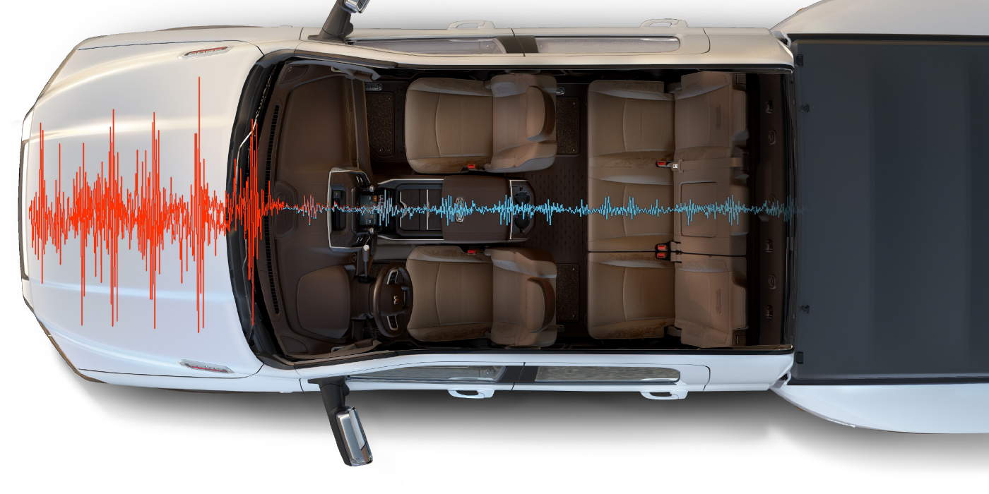
The variable-reluctor sensor (also called a “permanent magnet” or “pulse generator” sensor) is composed of a magnet wrapped with a coil of wire and placed close to a rotating reluctor. See Photo 2.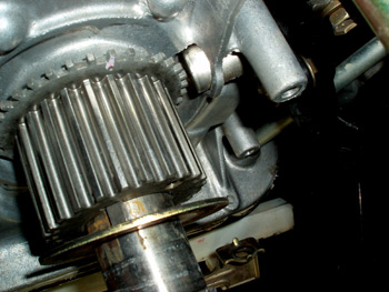
The voltage of the AC current generated by the variable reluctor varies according to the width of the gap between the reluctor and the sensor magnet and the speed of the crank or camshaft. If the gap is wider or the speed is slower than specified, the variable reluctor sensor may not produce a signal that can be read by the PCM or ICM. For those reasons, cranking speed on an engine is critical to generating a functional CKP signal.
Because a variable reluctor must also be able to count teeth on the tone wheel or reluctor, the teeth must be free of metallic debris. In many applications, the tone wheel might have a gap in the tooth sequence, which creates a “signature” pulse that the PCM uses to identify TDC position on number-one and its companion cylinder.
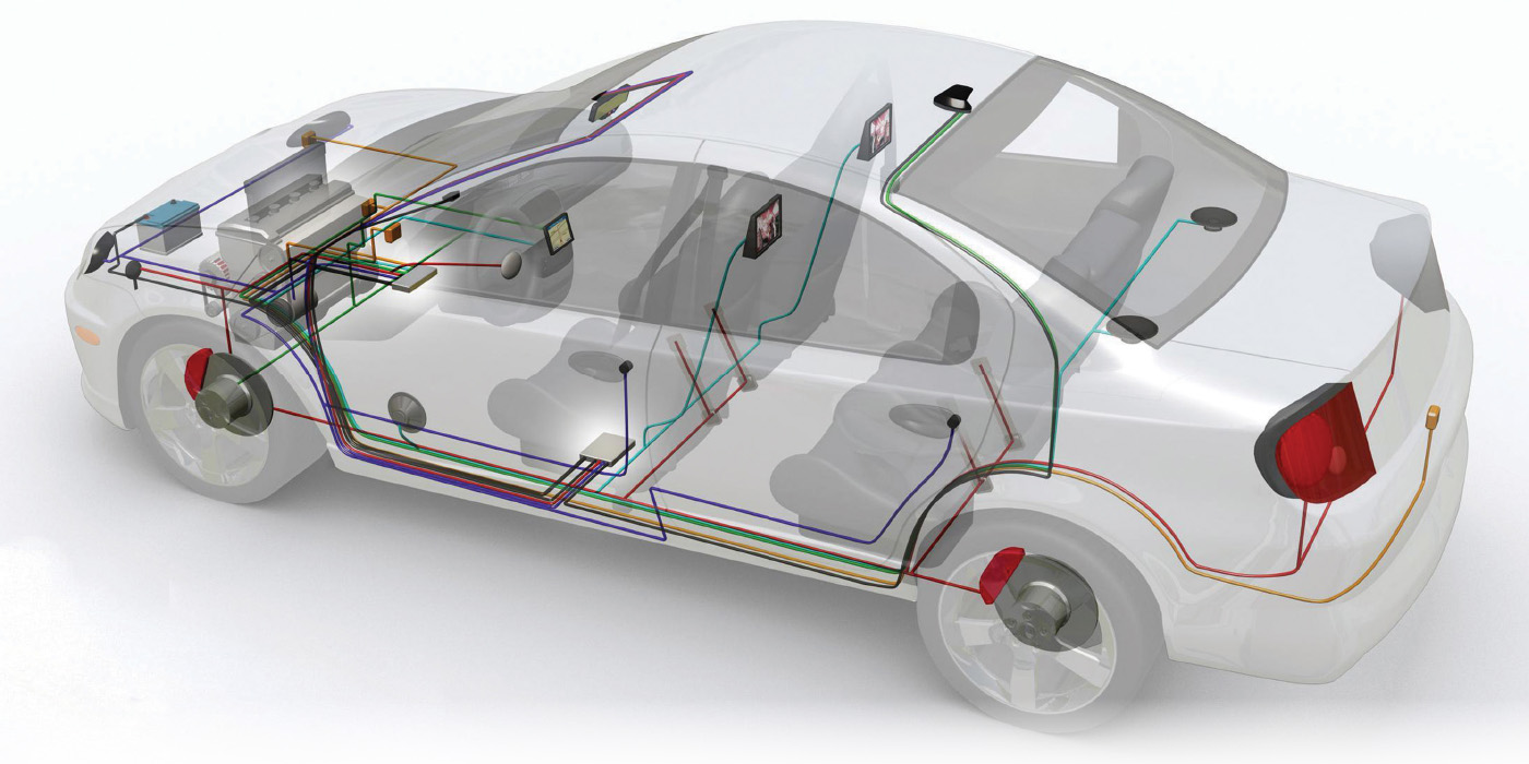
If the polarity is inadvertently reversed during manufacture or during a connector repair, the sensor output shifts from the leading edge to the trailing edge of the reluctor. Unfortunately, reverse polarity changes the timing event. In this case, the sensor might not place the signature gap in the correct sequence or might not see the signature gap at all. Such a condition might result in a no-start or rough-performance condition. As with all ignition sensors, the performance of the variable reluctor sensor is most easily evaluated with a digital storage oscilloscope (DSO). See Photo 3.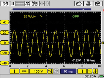
Variable reluctors are commonly used in crankshaft and camshaft ignition sensor applications and should be tested to specification for continuity, correct resistance and voltage output. A variable-reluctor sensor can be generally identified by its two-wire connector and the presence of a strong magnet at its core.
HALL EFFECT SENSORS
While the variable reluctor sensor functions as an electrical generator, the Hall Effect sensor functions as an electric switch. Unlike the variable reluctor sensor, the Hall Effect sensor requires an outside voltage feed wire to make it work.
In essence, a current is continually passed through a semiconductor in the Hall Effect sensor. When the semiconductor is exposed to a magnetic field, a small current is produced. When an interrupter ring or “shutter” is passed between the semiconductor and magnetic field, the current is turned on or off. Keep in mind that there are design variations in Hall Effect sensors. Some Hall Effect-type camshaft position sensors require a magnet built into the camshaft sprocket to generate a signal. See Photo 4.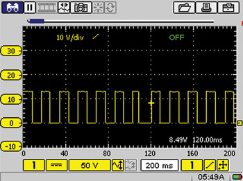
Because the shape of the square waveform is critical, Hall Effect sensors are best analyzed with an oscilloscope. While some ignition systems use a modified square wave to identify a timing signal, most require a conventional square wave to establish ignition-timing parameters. Some Hall Effect CKP sensors are actually two sensors – one high-resolution for idle conditions, and one low-resolution sensor for high-speed operation – integrated into one part. Each circuit should be tested as a separate sensor. The most important diagnostic feature of a “digital” square wave is that it pulls down to zero voltage in the “Off” position and reaches specified amplitude in the “On” position.
MAGNETO-RESISTIVE SENSORS
Because magneto-resistive or “MR” sensors are becoming more common in ignition applications, I’ll briefly cover the basic attributes of this system. First, the MR sensor is based upon the principle of a magnetic field changing the resistance and the current flow through the sensor itself. The MR sensor also consists of two MR sensors phased slightly apart from each other. Because of this difference in phasing, the MR sensor can measure shaft speed down to zero rpm and, in many cases, actually measure the position of the shaft when it’s stopped.
While the MR sensor produces a square-wave signal like the Hall Effect sensor, the square-wave signal will generally not pull down to zero volts. Instead, the signal will pull from high to low voltage as the circuit resistance changes. So, if you see a square-wave signal that behaves out of the ordinary, always be aware that technology can and does change with the times.