 VEHICLES: 2005-2008 Mustang
NOTE: This article supersedes TSB 06-4-1 to update the vehicle model years and Service Procedure.
ISSUE
Some 2005-2008 Mustang vehicles, built before 12/3/2007, may exhibit a concern with rattle/buzz/vibration from either the center stack (radio/heater) console, steering wheel, seat, floorpan and/or gearshift area.
ACTION
Follow the Service Procedure steps to correct the condition.
SERVICE PROCEDURE
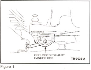
The rattle/buzz/vibration may be caused by one or both of the exhaust hanger isolators on the transmission cross member number 3 being loose in the bracket and/or compressed by misaligned exhaust hanger rod. If the voids in the isolator are compressed by the exhaust hanger rod, then it may allow the hanger rod to ground through the number 3 transmission cross member exhaust mount bracket (Figure 1). Follow the Service Procedure steps to correct the condition.
NOTE: V6 vehicles may have the rattle/vibration at approximately 850 rpm and 1,500 rpm; The V8 at approximately 1,200 rpm and 3,200 rpm.
NOTE: Refer to TSB
05-08-06 for 2005 4.0L Automatic trans vehicles exhibiting vibration/drone concerns.
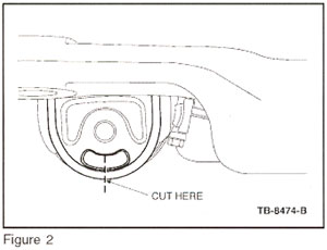
1. Using a suitable saw or cutting tool, cut the exhaust hanger rod isolator mount (and worm clamp if TSB 06-4-1 was previously performed) from the transmission cross-member as shown (Figure 2). The hanger rods/isolators are a production assembly aid and are not required. Do not cut off the hanger rod from the exhaust system.
2. Remove the mount pieces from the transmission cross-member. The isolator mount attachment tabs point towards the center of the vehicle.
3. Remove the isolator from the exhaust hanger rod.
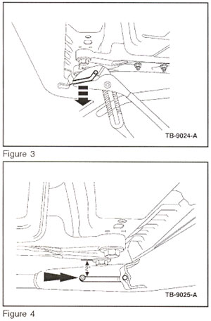
4.Bend exhaust hanger rod to a horizontal position to create approximately 2" (50 mm) clearance to the transmission cross-member (Figures 3 and 4).
5.Verify that the exhaust system is properly aligned by measuring the distance between the exhaust pipe and floor pan (behind the cat). The distance should be 2" +/- 0.5" (50 mm +/- 13 mm). If not, then align using the following instructions:
Exhaust System Alignment:
1.Loosen, but do not completely remove all four (4)catalytic converter-to-exhaust manifold nuts. The catalyst should now be loosely supported in the vehicle.
2.Position a jack stand underneath the catalytic converter Y-Pipe I H-Pipe.
3.Adjust the height of the catalyst using the jack stand to achieve the 2" +/- 0.5" (50 mm +/- 13 mm) clearance between the exhaust pipeand floor pan (behind the catalytic converter).
4.Evenly tighten all four (4)catalytic converter-to-exhaust manifoldnuts (starting with the right lower, then the left lower, then the right upper, then the left upper) in 7 lb-ft (10 N.m) increments to a final torque of 33 lb-ft (45 N.m).
5.Verify that the nuts on the coupler between the intermediate pipe and catalytic converter are torqued to 40 lb-ft (54 N.m).
Tech Tip courtesy of ALLDATA.