In 2007, the Ford Edge and Lincoln MKX crossover vehicles were introduced. The vehicles are based on the CD3 platform that is used for the Fusion and other Ford vehicles. While there are both FWD and AWD models on the streets, the alignment procedures are the same.
When you get one of these in your shop, the adjustments can be time-consuming, especially in the front. Make sure you charge enough for the alignment and explain to the customer why it is necessary.
Front Suspension
Camber is factory adjustable, but caster is not. In TSB 08-7-3, Ford advises technicians to look at camber specifications to solve pulling or steering wander problems. In a nutshell, the bulletin says that individual camber angles may exceed the specs, but if the cross-camber angles exceed the specs, it might cause a pulling problem.
Camber is adjusted through the use of the upper strut plate. Rotating the upper strut plate 180 degrees will change the camber a positive 0.5 degrees.
Make sure you do the math before starting the adjustment. The camber shift may vary between vehicles, but will typically be between a negative 0.2 and negative 0.6 degrees of camber change.
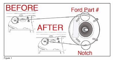
First, check to see if someone has already made the adjustment. On the inboard side of the strut tower, you will see a small round inspection hole. If you see letters and numbers, you can make the adjustment. If you see a notch that is painted white or yellow, the vehicle has already been adjusted (see below diagram).
To make the adjustment, disconnect the front stabilizer bar link at the lower control arm so that enough clearance can be obtained to rotate the upper strut mount.
The warranty time on this procedure is 1.4-1.8 hours for both sides. A better option is to replace the upper strut-to-knuckle bolt with cam bolts. The labor time to install these bolts is 0.4 hour per side. The bolts will allow you to precisely adjust the camber by ±1.75º. This can be a real time-saver when trying to solve cross-camber conditions.
Unlike with the Fusion, the cradle cannot be shifted to change camber and caster angles on these units. If the caster is out of specification, chances are it is a worn or damaged control arm rear the bushing.
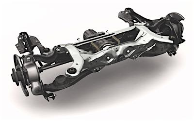
Rear Suspension
The rear suspension camber and toe are adjustable without any parts or kits, but there is a catch — the inboard-rear cam bolt attached to the lower link has significant “cross-talk” with the toe angle. When adjustments are made to the rear toe, the rear camber will also be adjusted (in the same direction as the toe adjustment). Likewise, when making adjustments to the rear camber, the rear toe will also be adjusted (in the opposite direction of the camber adjustment). So, it will be necessary to check the rear camber whenever rear toe adjustments are made and vice versa.
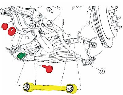
Toe is adjusted with a cam bolt on the inboard side of the toe link. The toe adjuster will have a greater affect on toe than the rear adjuster. A successful method is to adjust camber using both adjusters until camber is correct and toe is at, or near, zero. Use the front adjuster to fine-tune the toe adjustment. The camber adjustment should stay close.
TPMS
All Edge and MKX models come with direct TPMS systems, and 2007-’09 models have banded sensors. In 2010, Ford made the transition to valve stem-mounted sensors. Model year 2007-’08 Edge and MKX units were included in a campaign to replace the tire valve stems. If you have a customer who is complaining about a slow leak, chances are it is a result of the valve stems.
Activation
- Turn the ignition switch to the ON position.
- Position the TPMS tool against the LF tire sidewall, 180 degrees from the tire valve stem. The TPMS tool must remain in place 180 degrees from the valve stem for 2007-’09 models with banded sensors, and directly below the valve stem on the sidewall for 2010-’11 models with the valve stem-mounted TPMS sensors.
- Note: The TPMS tool will provide feedback in the form of a flashing green light and a beep sound for each successful response from a tire pressure sensor. Press the test button on the TPMS tool to activate the sensor. Activate the sensor at least two times.
- Repeat Steps 2 and 3 for the remaining tires.
Relearn
- Turn the ignition switch to the OFF position. Then, press and release the brake pedal.
- Cycle the ignition switch from the OFF position to the RUN position three times, ending in the RUN position.
- Press and release the brake pedal.
- Turn the ignition switch to the OFF position.
- Turn the ignition switch from the OFF position to the RUN position three times, ending in the RUN position. The horn will sound once, and the indicator will flash if the training mode has been entered successfully. If equipped, the message center will display “TRAIN LF TIRE.”
- It may take up to six seconds to activate a tire pressure sensor. Press and release the test button on the TPMS tool. The horn will sound briefly to indicate that the tire pressure sensor has been recognized by the vehicle.
- Within two minutes of the horn sounding, place the TPMS tool on the correct position for the sensor and release the test button to train the right front tire pressure sensor.
- Do not wait more than two minutes between training each sensor or the Smart Junction Box (SJB) will time out and the entire procedure will have to be repeated. Repeat Step 7 for the right rear and then left rear.
The procedure is completed after the last tire has been trained. When the training procedure is complete, the message center (if equipped) will display “TIRE TRAINING COMPLETE.” For vehicles that are not equipped with a message center, successful completion of the training procedure will be verified by turning the ignition switch to the OFF position without the horn sounding. If the horn sounds twice when the switch is turned to the OFF position, the training procedure was not successful.