Model: 2005-’07 Super Duty
Some 2005-‘07 Ford Super Duty vehicles may exhibit an ABS light on and possible diagnostic trouble codes (DTCs) C1175, C1236, P0500 and/or P0503. This condition may be due to faulty vehicle wiring, a failed wheel speed sensor or vehicle speed sensor (VSS) tone ring damage inside the rear differential case. The base brake system will continue to function as normal.
 Service Procedure
P0500 and/or P0503
The P0500 and P0503 are set by the PCM when the VSS signal from the ABS module is missing. If the vehicle has DTC P0500/P0503 in the PCM, and the vehicle has ABS DTCs, check ground 105 and the ABS fuse (mini fuse No. 11).
C1175
If the vehicle has only DTC C1175 in the ABS module, it is most likely caused by a wiring concern or a faulty sensor.
1. Inspect the vehicle wiring for damage beginning at the rear WSS connector and ending at the ABS module. Damage may be at any point in the wiring.
2. Inspect for pinched looms, frayed terminal connections, loose pins, etc.
3. Pay special attention to the wiring along the frame (especially if the vehicle has been modified from a body builder), and near the fuel tank.
4. The speed sensor wiring begins at the rear axle and is routed along the frame rail on the left side of the vehicle. It then branches off at C140 (gas C133), which is located beneath the master cylinder. The wiring then goes to C455 at the ABS module.
5. The wiring should not be loose, especially near the rear WSS. Ensure that the wiring is properly retained and routed to eliminate intermittent speed signals.
Note: Use a zip tie to secure the harness to the sensor so the portion of the harness that is coming off of the brake cable is supported.
6. Repair wiring as necessary. If no concerns are found in the wiring, replace the sensor.
C1175 and C1236
If the vehicle has DTCs C1236 and C1175 in the ABS module, check the vehicle wiring per the C1175 procedure. If there is a hard or intermittent wiring fault, the current may at times be high or low causing a C1175. A wiring concern may also cause noise in the circuit that can be interpreted by the module as an erratic speed signal, which will set the C1236.
If no wiring issue is found, follow the C1236 procedure below.
C1236
1. If the vehicle has DTC C1236 in the ABS module, a wiring concern may exist that is severe enough to interrupt the signal, but not severe enough to totally open/short the circuit. Inspect the sensor connector on the 14405 harness for corrosion, a broken/cracked connector or signs of water trapped in the strain relief elbow. Install a new pigtail if necessary (See pigtail installation procedure below).
2. Ensure that the harness is properly retained and routed to eliminate intermittent speed signals.
3. Add dielectric grease to the connector.
4. If only DTC C1236 exists, and it occurs only under acceleration or towing, check for loose carrier bolts.
5. If no wiring concerns are present, check the tone ring through the WSS bore for damage and for proper gap between the tone ring and ring gear.
6. Use a feeler gauge to confirm that the gap between tone ring and ring gear is no larger than 0.010″. Check the gap at multiple locations around the tone ring.
a. If gap is larger than 0.010″, remove the axle cover and use suitable punch/driver to carefully tap the tone ring back against the ring gear. Recheck with feeler gauge.
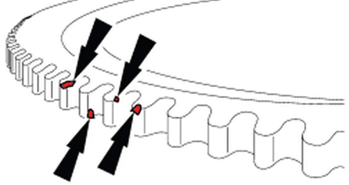
b. Examine each tooth of the tone wheel for damage. Even a small nick can cause a C1236 (Fig. 1).
7. If no tone wheel issues are found, replace the WSS.
Pigtail Installation
1. Disconnect the battery.
2. Disconnect the damaged connector from the axle.
3. Cut the wiring near the rear wheel sensor takeout from the 14405 harness.
4. Splice in the pigtail (pigtail includes heat shrink).
5. Cover the heat shrink with tubing.
6. Route the two retainers of the pigtail to the park brake cable.
Note: Use a zip tie to secure the harness to the sensor so the portion of the harness that is coming off of the brake cable is supported.
7. Plug in connector to rear wheel sensor and check for functionality.
Courtesy of Identifix.