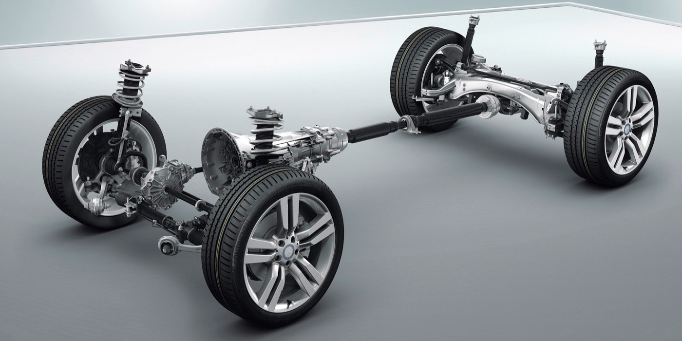
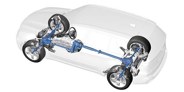
Electronic automatic transmissions have gained popularity in recent years because of the flexibility that on-board electronics can provide in the area of powertrain management. Electronic transmission controls, for example, have done away with the rough, imprecise shifting patterns inherent in early mechanically controlled transmissions. With the continued refinement of electronically controlled automatic transmissions, an automatic can usually be made more fuel-efficient for average daily driving than its manual transmission counterpart.
TORQUE CONVERTER BASICS
The concept of using a torque converter, oil pump, planetary gear sets, clutches, bands and a computer-controlled hydraulic valve body to transmit torque and to change gear ratios is relatively simple. To illustrate, the torque converter allows the engine to idle in gear with the vehicle stopped and multiplies engine torque during the initial stages of acceleration. In addition to an electronically controlled clutch that prevents the torque converter from slipping during cruise conditions, the primary parts of the torque converter are the impellor, stator and turbine.
Each of these parts has a set of curved vanes that accelerates and controls the flow of oil in the torque converter housing. The impellor, which is driven by the engine, uses centrifugal force to push oil into the turbine. The turbine, which is attached to the transmission input shaft, receives the impact of the rapidly moving oil to develop a torque input to the vehicle’s drivetrain.
The difference between the speeds of the impellor and turbine is called stall speed. Generally, stall speed is limited to 1,500-2,000 rpm to prevent over-heating the transmission oil. Torque converter hydraulic “lock-up” occurs when oil velocity in the converter is high enough to keep the impellor and turbine rotating at nearly the same speed.
The stator, which is attached to the transmission front oil pump assembly, contains a one-way roller clutch assembly that locks the stator in place during acceleration and allows it to freewheel during deceleration. During acceleration, the impellor is rotating faster than the turbine. The stator redirects oil from the turbine into the faster-rotating impellor blades to multiply torque. During deceleration, the direction of oil flow in the converter reverses because the turbine becomes the driving component. The stator must then freewheel to allow the oil to reverse its direction of flow.
AUTOMATIC SHIFTING BASICS
As with the older mechanically controlled automatic transmissions, the electronic transmission uses engine load and vehicle speed inputs to select each gear range. The combined data from the air flow, manifold vacuum, barometric pressure, throttle position and crankshaft position sensors are generally used by the PCM to calculate engine load. Similarly, the anti-lock braking sensors located at the wheels or a speed sensor located on the transmission output shaft provides a road speed input to the PCM.
The PCM controls shift solenoids that are attached to the hydraulic control valve body of the transmission. The valve body contains a shift valve for each gear range. By commanding a shift control solenoid to increase or decrease oil pressure at the shift control valve, the PCM can force the shift valve to change gear ratios by hydraulically engaging or releasing a clutch or band assembly attached to the planetary gear sets. Each planetary gear set can create a direct, reduction or reverse-gear ratio, and more gear ratios can be created by using more planetary gear sets.
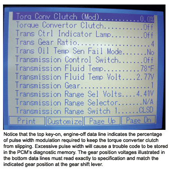
Modern electronic automatic transmissions use pulse-width modulated solenoids to control the engagements of the torque converter clutch and shift valve solenoids. By using pulse-width modulation, the timing and firmness of clutch pack and band engagements can be varied to accommodate diverse driving conditions and to even compensate for wear in the transmission itself.
 DIAGNOSTIC SUMMARY
Although most import shops choose to replace automatic transmissions or refer internal repairs to import transmission specialists, many in-car repairs can be accomplished using an applicable scan tool to retrieve DTCs. To illustrate, the input and output shaft speed sensors indicate the difference between input and output shaft speed to the PCM. If the difference between input and output speed is greater than the selected gear ratio, a DTC is stored in the PCM’s diagnostic memory and the “Check Engine” warning light will be illuminated.
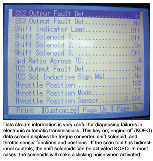
In general, most problems in an electronic automatic transmission will be caused by a low power supply from the ignition switch, a faulty input or output speed sensor, or a shift control or torque converter clutch solenoid failure. Bi-directional controls on a scan tool can be used to actuate shift solenoids in an engine-off, key-on mode.
Oil level and condition is critical in any transmission diagnosis. Although the dye color of the oil might normally fade with time, the key indicator of a mechanical failure in a modern automatic is blackened oil on the dipstick. Frictional residue in the oil pan was common on early mechanically controlled transmissions because clutch and band timing overlap caused excessive wear to take place. Frictional residue found in the oil pan of a more precisely controlled electronic unit might, however, indicate a potential mechanical failure in the transmission. With the exception of the iron filings from normal gear train wear found on the collection magnet in the oil pan, non-ferrous, metallic residue or particles usually indicate a bushing, roller clutch or thrust washer failure.
 TRANSMISSION SERVICE
Oil maintenance is critical to the life of an electronic automatic transmission because even modern synthetic oils tend to oxidize and lose their additive packages due to time, moisture exposure and hard use. Unlike engine and gear oil, automatic transmission oil must lubricate while at the same time maintain frictional properties that keep clutch packs and bands from slipping under load. In addition, the oil must prevent varnish and corrosion from accumulating on the precision-made shift valves located in the valve body, and must be compatible with all non-metallic and frictional components of the transmission.
In general, the manufacturers’ service intervals are adequate for most driving conditions. Exceptions to those driving conditions might include trailer towing, off-road use or exposure to high-humidity driving situations. A thorough transmission service should include shift linkage and electrical connector inspection, re-torquing valve body screws and bolts, filter replacement and a thorough flushing using the correct oil for the application. Following service, the vehicle should be test-driven and the oil level checked with the oil hot to the touch and the vehicle resting on a level surface.
CONSTANT VARIABLE TRANSMISSIONS
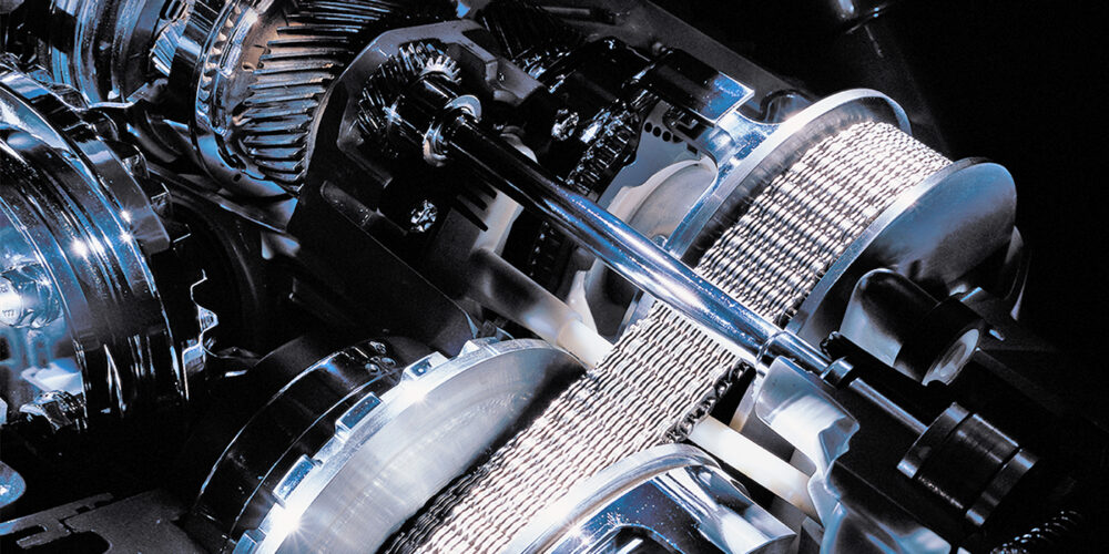
Constant variable transmissions (CVTs), which are now common in many smaller imports and in some hybrid applications, are driven by a steel V-belt running on two infinitely variable ratio pulleys. The CVT’s virtue is its ability to maintain an engine’s speed at the peak of its torque output curve, which is the point at which the engine produces the highest torque output with the least fuel consumption. When combined with electronic transmission controls, the CVT becomes a very flexible and reliable transmission design.
Because current CVT designs use a steel chain rather than a rubber V-belt to transmit torque, lubrication requirements are critical. In short, oils used in CVTs are designed to lubricate under low loads, but provide a high frictional coefficient under high loads, such as that found between the steel drive belt and its drive pulleys. For this reason, the oil in a CVT must not be diluted by topping off with non-recommended oils. In addition, many CVTs aren’t field-repairable units and must be replaced as a new assembly.

