Five years ago, I began seeing a very small number of General Motors products come through the door with a variety of trouble codes indicating a “circuit failure” in the intake air temperature (IAT) sensors, mass air flow (MAF) sensors, throttle position (TP) sensors and idle air control (IAC) systems. In all cases, these failures were intermittent or random failures that were difficult to duplicate, which required one or more return visits before I could pinpoint the problem. Most had circuit failure codes and one had no codes at all.
What was the problem? After much trial and error and a great amount of frustration on my part, I found that all of these failures were caused by a wire losing continuity inside the insulation or at a terminal evidently crimped over the insulation on the wire. Not that this is a common failure; as a matter of fact, it’s relatively rare. In 40 years of repairing motor vehicles, I had previously encountered this condition only once or twice.
The History of Wiring
For the most part, the electrical wiring found in most automotive systems is very dependable. In the late 1980s, a few Ford and Chrysler products had a problem with the insulation peeling off the wire’s copper core when exposed to petroleum-based fluids and vapors. Some of the old ’80s Ford products also had wiring splices within their wiring harnesses that would separate when the wiring harness was stressed during an engine replacement or repair. For a short time, Chrysler resisted the use of weather-proof connectors on some of its early electronics systems and suffered proportionately from corrosion issues on these connectors.
From my perspective, General Motors wiring has been relatively trouble-free until engineers began using small-gauge wiring to connect various sensors to the PCM. Small-diameter wiring has much less mechanical strength and, for the field mechanic, is much more difficult to diagnose and repair. If a technician pierces a small-gauge wire to test a circuit, he more than likely has created a potential stress failure in the copper wire itself, not to mention exposing the wire to corrosive fluids and moisture through the opening punched through the insulation.
The High-Revving Plumber’s Van
My first case study involving a hard-to-solve wiring failure is a 2003 Chevrolet 2500 series cargo van with 77,734 miles on the odometer that is used by a local plumbing company to transport equipment and materials to various job sites. The van is a two-wheel-drive model with a numerically low rear axle ratio. The complaint was that the driver would overheat the brakes because the engine would “fast-idle” going downhill. After several adventurous episodes of traveling down steep mountain roads with smoking brakes, the driver decided to have the van repaired.
During the first visit, the van had no diagnostic trouble codes (DTCs) stored other than some codes in the anti-lock braking system caused by defective wheel speed sensors. At this point, I had no other data that would provide a diagnostic direction other than having a number of 1990s-vintage Chevy trucks come in with fast idle problems caused by a faulty throttle position sensor. At this point, I cleaned the throttle body assembly and made sure that the throttle cable wasn’t binding and let the vehicle go back to work.
Operating Strategies I
Understanding operating strategies is essential to diagnosing faults in modern vehicles. To illustrate, the PCM may “learn” the closed-throttle TP sensor voltage the instant the ignition is turned on. For each succeeding closed-throttle event, the PCM must “see” the TP sensor return exactly to the voltage value stored in its memory. If closed-throttle TP voltage fluctuates as little as a few hundredths of a volt, the PCM might revert to a default strategy of fast-idling the engine at about 1,200 to 1,500 rpm to prevent a potential engine stall.
Unfortunately, the old saying that we’re all a victim of our own experiences was the case on the 2003 Chevy plumber’s van. Back for its second visit, the van’s PCM had stored a P0507 DTC indicating that idle speed was higher than expected during one event in which the freeze-frame data for the P0507 indicated: 0% throttle, 187° F ECT, 0 mph, 5% load, 9.84 grams mass air flow and 1,378 rpm idle speed. Although the condition had occurred while the vehicle was parked, it hadn’t been reported by the driver.
Because of my previous experiences with fast idle conditions and of the plumbing company’s desperate need for the truck, I decided to gamble on installing a new TP sensor. A few phone calls later revealed that the TP sensor was available only as part of a rather expensive throttle body assembly. Of course, the TP sensor had passed a lab scope sweep test in both cold and hot operating modes. Because the problem was occurring on a random basis, I couldn’t dismiss the TP sensor as a source of the high idle speed condition. Nevertheless, the price of the throttle body assembly dissuaded me from experimenting with a TP replacement.
Operating Strategies II
At this point, the only diagnostic data I had was a DTC that told me that the engine was idling too fast for a particular operating condition. The other bit of information was that the TP had passed various sweep tests with flying colors. Those two bits of information left the IAC motor as the only other prime suspect in causing a condition that I had yet to duplicate. Could the IAC be mechanically sticking in the open position? Yes, but the IAC was, again, available only as part of an expensive throttle body assembly. On the other hand, what about the operating strategy of the IAC itself?
The only time the plumber noticed the fast idle condition was traveling downhill. At no other time did he mention a fast idle condition. Keep in mind that, in most cases, the IAC tends to pull full-open during open-throttle operation. This strategy allows the PCM to better anticipate and control idle speed when the vehicle comes to a stop. Keep in mind also that using the engine for braking reverses the torque stress on the engine mounts. So, with these facts in mind, could an open-circuit failure in the wiring harness cause the IAC to remain in the open position? The answer is “yes” because the PCM can no longer command the IAC to a closed position when the vehicle is coasting under a closed-throttle condition.
Invasive and Non-Invasive Diagnostics
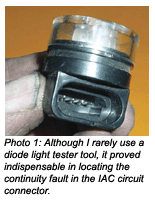 The problem with diagnosing a four-wire IAC circuit using small-gauge wire is that using any invasive procedure such as piercing such a small wire might create still another problem. If a pin is stuck into the IAC connector or even the PCM connector to get a scope or DVOM reading, the process might also temporarily correct a terminal connection problem. So how could I prove that the wiring was the source of the problem? The answer was to use a tool that incorporates diode lights to indicate the presence of commands from the PCM to IAC. After removing the IAC connector and inserting the diode light tester, I wiggle-tested the IAC pigtail and discovered that one diode light would turn off when its corresponding wire was slightly bent in the direction of engine torque reversal. See Photo 1.
After explaining the situation to the plumbing company, authorization was granted to install a new IAC pig tail to remedy the fast-idle complaint. One year later, the plumbing van has experienced no further fast-idle complaints.
The Choking Resort Bus
This past summer, a neighboring shop asked me to diagnose a 2003 6.0L Chevy 3500 HD passenger van with 38,503 miles on the odometer that was intermittently running rich at idle and low speeds. Current codes were P0106 (MAP/BARO range or performance problem), P0121 (TP sensor range or performance problem) and P0300 (Random misfire problem).
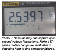 I duplicated the complaint for about five minutes during the first visit. The van developed a very rich rolling idle. The scan tool data stream showed a TP voltage that was changing so rapidly that the data line became a blur. At this point, I attached my Fluke 187 DVOM to the TP sensor output wire and placed it on min/max to record minimum and maximum voltages. I use the 187 because it’s capable of recording electrical glitches that occur in less than a few millionths of a second. The Fluke 187 showed a minimum of about 0.80 volts and a maximum of 2.5 volts at idle. See Photo 2.
Going back to the DTCs, the over-rich air/fuel mixture was not only causing the engine to misfire, but also was driving the MAP/BARO readings beyond their normal parameters. Here again, I was faced with pulling a rabbit out of the hat for a resort with customers anxiously waiting to depart to an airport located 125 miles away. That issue, and because I could no longer duplicate the complaint, left me with replacing the TP sensor as a first step in the diagnostic process. My rationale was that the TP sensor had shorted internally, driving the output voltage to 2.5 volts at idle. Of course, most diagnostic techs never get that lucky, myself included.
At the end of our tourist season, the van was returned for a more thorough diagnosis. This time, of course, I couldn’t duplicate the rich rolling idle condition cold or hot. The original data provided by the Fluke 187 meter couldn’t be denied, however. But, with the TP sensor replaced and the condition reoccurring, it was obvious that the fault probably lay with the data wire reporting TP output voltage to the PCM or with the PCM itself.
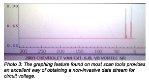 Here again, the question became how to prove the wiring failure using a non-invasive method that would neither aggravate nor temporarily cure the problem. The answer was elegantly simple. Using the graphing feature on my scan tool, I began performing a wiggle test on the TP sensor wiring. Suddenly, the TP voltage spiked up from its normal value of 0.55 volts to about 0.90 volts. This would indicate that the TP sensor’s ground wire might be losing continuity, since the voltage level at the PCM had spiked upward instead of to zero. See Photo 3.
The change was small, but indicative of what I was looking for in a broken wire or terminal connector. Here again, I solved the complaint by replacing the pigtail on the TP sensor.
Diagnostic Summary
Always remember that any sensor circuit consists of two or three wires that allow the sensor to modify the original reference voltage into a signal that the PCM can read as data input. The only difference between a two- and three-wire circuit is the inclusion of a floating ground wire to the PCM that maintains the accuracy of the voltage signal. So, if a circuit failure occurs, it must be determined if the fault lies with the PCM, sensor or wiring.
In most cases, the continuity failure in the wiring will be found near the connector. This could be attributed to damage caused during manufacture when the terminal is crimped to the wire. Although I have, on one occasion, found a continuity failure deeper in the harness on a 2003 Chevy Astro van MAF failure, I begin wiggle-testing at the connector.
While saying this, experience will show that wiggle-testing a connector will produce very minor, but normal variations in circuit voltage. In one case of a ’96 Chevy Blazer that had three new TP sensors installed to cure a TP circuit failure, I ultimately found that a slightly corroded connection at the PCM connector was responsible for the variation in TP sensor voltage.
Last, graphing voltage changes with a scan tool is perhaps the most effective and non-invasive method of detecting continuity failures in wiring circuits. Because no scan tool data stream is included for individual circuits on the IAC mentioned in my first case study, I had to resort to the diode tester to find the continuity failure. During my second case study, the Fluke 187 was the quickest way to get real-time data on the wildly fluctuating voltage values emanating from the TP sensor circuit. In any case, no single method fills all diagnostic requirements and that’s what diagnostic creativity is all about in this day and age of increasingly complex on-board electronics.