We all know brakes get hot, sometimes very hot. If you watch closely on race day, it’s not uncommon to see the rotor on a race car glowing bright orange. Iron is in the range of 1,700º F when orange.
 At the most basic level, a brake is an energy conversion device. Normally people will equate temperature with speed. While this is generally true, it is more accurate to associate heat with energy. Today’s cars are filled with energy conversion devices.
Virtually all of the things a car does results from the chemical energy of the fuel or the battery being converted into some useful and desirable function for the driver and passenger. The engine, brakes, heater and radio are a few examples.
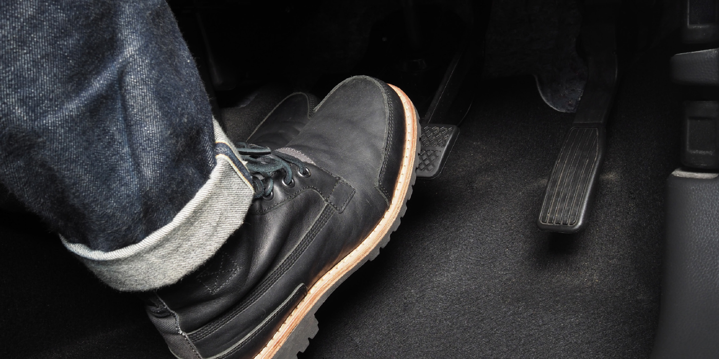
The job of the brakes is to convert the energy of a moving vehicle into heat resulting in the vehicle reducing speed.
Stopping with Horsepower
One of the basic physical laws of the universe is that all energy is conserved. In simple terms, energy can’t vanish. It can change forms, perhaps multiple times, but it is always somewhere. The engine, through the combustion process, converts the chemical energy of the fuel into heat that moved pistons to accelerate a vehicle to some speed or altitude. We rely on the brakes to stop us, now.
Consider a typical midsize SUV loaded to its gross vehicle weight of approximately 6,400 lbs. While traveling at 60 mph, it has a “kinetic” energy equal to 988 British Thermal Units or BTUs. This is calculated according to the equation for energy of motion.
Energy (Kinetic) = 1/2 x Mass x (Velocity)2
 When this vehicle is stopped, the kinetic energy is transferred into the brakes resulting in an increase of the rotor temperature. Time is also a big factor. If that SUV is stopped at its maximum capability of approximately 140 feet, then this energy must be absorbed in about three seconds.
The amount of energy transferred in a given period of time is power. The faster the energy must be transferred or absorbed requires additional power. In this example, the brakes must absorb about 465 HP.
Thermal Management
Recall the energy and thus the power increase by the square2 of the velocity. As a result, the brake system design engineer must design the system to absorb the vehicle’s energy and power from the maximum speed that the vehicle is capable of.
Those brakes for that same SUV at its maximum speed of 110 mph must absorb more than 800 HP or approximately three times what the engine is capable of producing.
Consider what these numbers become for the 747 jumbo jet touching down on the runway and coming to a stop. Same equations, just a lot more zeros on the end.
A related condition the brake system engineer must consider regarding thermal performance is the repeated braking or performance braking condition. This is really just a special case of the kinetic energy situation. In general, the engineer must design his brakes around a specific performance profile. They all generally consist of repeated acceleration and braking over multiple stops as quickly as the vehicle will accelerate and brake. Sometime this is referred to as a “fade test.”
 Mathematically, the fade is an extension of the kinetic energy equation. The energy of each stop is defined by the equation Energy (Kinetic) = 1/2 x Mass x (Velocity)2 and added up. The brake system engineer can mathematically calculate the energy his brakes must absorb and dissipate. Using this information along with assumptions and calculations about how quickly the hot rotor can transfer its heat energy to the surrounding air, he can estimate the peak temperature of his components.
Ultimately, in the vast majority of cases he must prove with a real test and real parts how hot the parts get and that nothing bad happens when the parts get that hot.
Single Stops
The single stop from maximum vehicle speed is a relatively simple and straight forward test. On a high-speed test track, the vehicle is accelerated to its maximum speed and braked in one continuous event to a stop.
The manufacturer will define its expectations for the rate of deceleration. This is generally between 0.50g of deceleration up to the maximum deceleration the vehicle is capable of. This is an important factor as this determines the amount of time associated with the energy conversion. The energy of a Corvette at 140 mph is constant. The power necessary to stop it at maximum deceleration is approximately double than if allowed to stop at 0.50g.
The key goal of the test is to ensure that the brake system can operate in this environment and that the heat generated does not damage the components to an unacceptable level. As a result, the vehicle is heavily instrumented with thermocouples (a simple device that measures temperature in a specific spot) and reports it to a data acquisition system.
 It is important to be able to measure temperature in very small time intervals and in many places. The temperature can vary widely within a small distance. The peak temperature measured at the components and how long it stays above a certain temperature are compared to the particular material specifications for compliance.
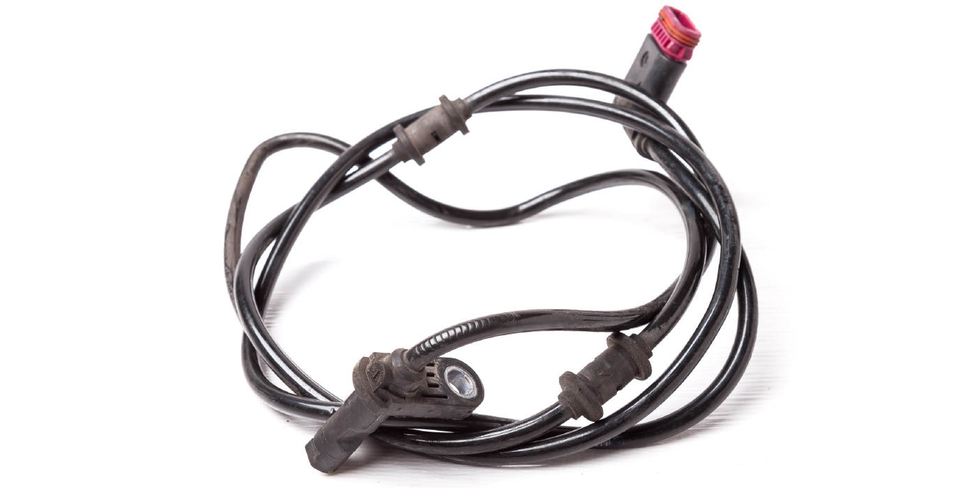
Typically, things like melting of speed sensor wires, caliper dust boots and steering tie-rod boots are evaluated. In addition to visually obvious failures, things like the thermal limits of the electronics in the speed sensor are also validated.
Electronic and rubber components are generally rated in the amount of time they can be exposed to a particular temperature. The components can be permanently damaged or become non functional at temperatures well below their melting or ignition temperature.
 Why Rotor Design Matters
The “Single Stop from Maximum Speed” test only takes a few seconds to complete. As a result, the temperature in the components, especially the rotor, rises very quickly. Fast temperature increases (or decreases) result in high thermal stress. Simply stated, these are the forces that result from small portions of the part changing temperature at different rates.
As each part is trying to grow, it wants to tear itself away from adjacent parts. As a result, it is critical to test to evaluate the structural integrity of the rotor in these types of situations. The rotor must be inspected for cracking or “heat checking.”
The thermal mass of the rotor will generally govern the peak temperature of the rotor. Thermal mass is defined as the weight of the plates and fins. The hat and wheel mounting face are not considered part of the thermal mass of the rotor. Thermal mass will generally be approximately 85 percent of the total weight of the rotor. The design of the rotor cross sections is a critical design control.
 Subtle details of fin and plate geometry can significantly affect the structural integrity of the rotor. As a general rule, thick sections adjacent to thin sections and sharp corners should be avoided. Two rotors of equal thermal mass may reach virtually the same peak temperature, but have very different structural integrity characteristics.
The material grade and associated properties of the iron are also critical and can vary widely in the market.
Technicians should inspect replacement rotors carefully and compare them in detail to the OE rotor to ensure that thermal integrity can be maintained. Aftermarket rotors that are significantly lighter or have substantially different fin configurations should be viewed cautiously.
In the single stop situation, the rotor heats up very quickly, but is then given the opportunity to cool for extended periods of time. As a result, the energy that is temporarily stored in the rotor is predominantly transferred to the ambient air. To satisfy the rule of energy conservation, the air temperature will rise until the two are in equilibrium.
Air and Heat
Due to the virtually infinite volume of air, in practical terms, the air absorbs the heat until the brake components returns ambient temperature.
Very little of the energy transfers to the surrounding components in the single stop case. As a result fluid boil is generally not experienced. The situation changes dramatically when the system engineer must confirm the brake system can handle the energy absorption required to bring the vehicle down a long grade.