
The Cadillac ATS incorporates many technologies GM introduced in the past decade. The engineering of the ATS’s brake system is one of the best for noise, durability and safety.
There are two brake packages for the ATS. The base JE5 uses single-piston calipers in the front and rear. The J55 or J6 is typically found on the ATS-V, and uses larger rotors and a four-piston caliper in the front. There is also an option for a more aggressive track pad on the ATS-V.
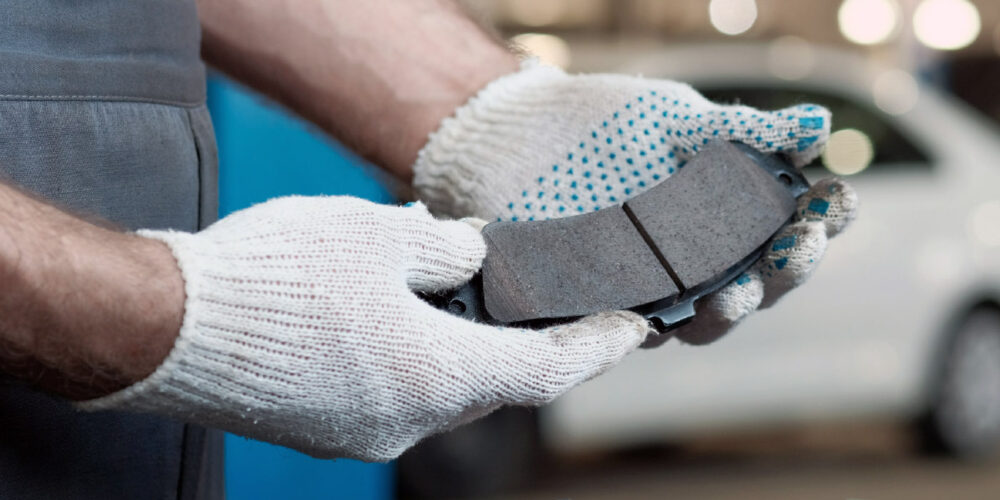
Pads
The brake pads on the ATS are engineered to work with the rotors. The formulation of the base brakes use a ceramic or non-asbestos-organic formulation. Using aggressive semi-metallic pads could reduce the life of the rotor. Use a high-quality pad for the ATS that is designed to work with the rotor.
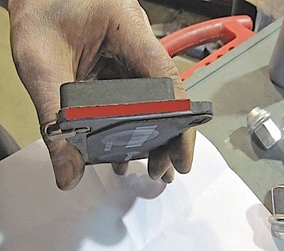
On vehicles with the J6 performance brake package, the customer may complain of noise when the brakes are first applied. GM recommends applying a moly-lubricant to the ears and edges of the brake pad and advises not to apply to the back of the pad.
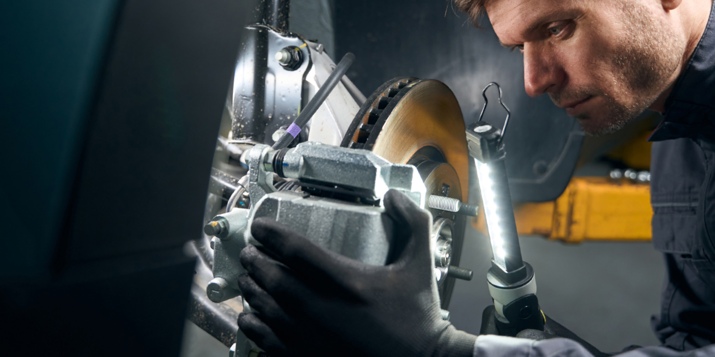
Calipers
The calipers on the ATS are very conventional and easy to service. But, the caliper bracket bolts are torque-to-yield (TTY). The tightening procedure for the front bolts is to tighten to 111 ft/lbs and then turn the bolt 30º. In the rear, the bolts need to be tightened to 74 ft/lbs and turned 25º. These fasteners should not be reused.
TTY caliper bracket bolts need to be installed dry. Do not apply any oil, grease, assembly lube or sealer on the threads. The reason why is that lubricants reduce friction when a bolt is tightened.
Do not use an impact wrench. Most impacts can generate twice the torque needed for the initial torque setting. If a TTY fastener is over-tightened, it can stretch beyond its limits and break.
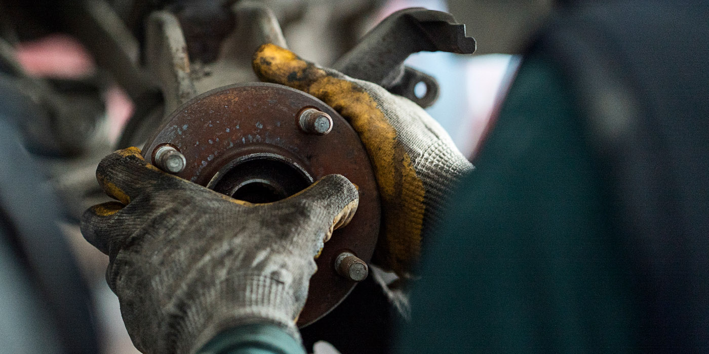
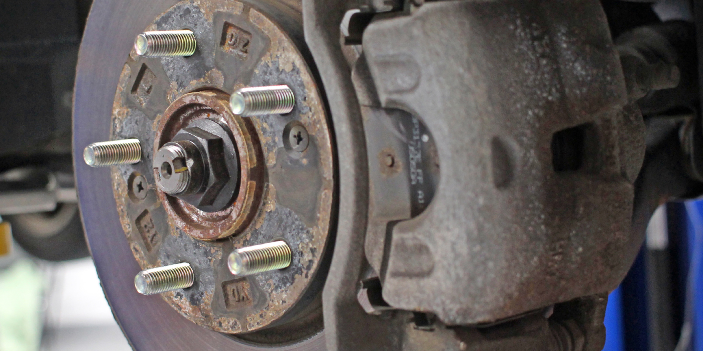
Rotors
On the ATS, GM has introduced a new brake rotor technology called Ferritic Nitro-Carburizing (FNC). Simply put, it is an additional step in the manufacturing process of the brake rotor that creates a hardened outer layer on the surface of the rotor. This hardened outer layer reduces the rotor rusting (corrosion), and it also allows the rotor to wear slower. Because this new technology protects against excessive rotor corrosion, it not only aesthetically looks better through open-spoke-type wheels, but helps reduce thickness variation, which creates pulsation specifically due to “lot rot” corrosion (when the vehicle sits on the dealer’s lot between build delivery and customer delivery).
If the customer complains about pulsation or judder, do not machine the rotor. GM recommends burnishing the brakes by performing 10-15 moderate stops from 35 mph, with cooling time between stops. This will help to put a fresh layer of friction material on the surface of the rotor and eliminate uneven accumulations.
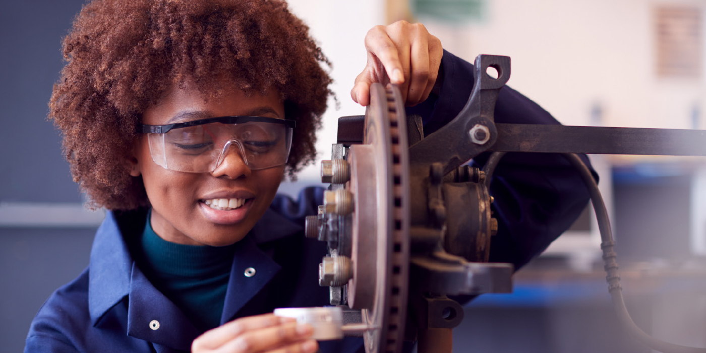
The rotors should only be machined if they are scored with grooves in excess of 1.5 mm, have lateral runout exceeding 0.080 mm (0.003”), or there is thickness variation in excess of 0.025 mm (0.001”).
When rotor machining is necessary, it is essential that you use a high-quality on-the-car brake lathe. In some cases, lateral runout can be corrected using shims or correction plates that fit between the rotor and flange. They can minimize runout in excess of 0.125 mm (.005”).
When replacing the rear rotors on models with a electronic parking brake, it might be necessary to disengage the electronic parking brake. This can be done with a scan tool or using the following procedure:
1. Block the drive wheels.
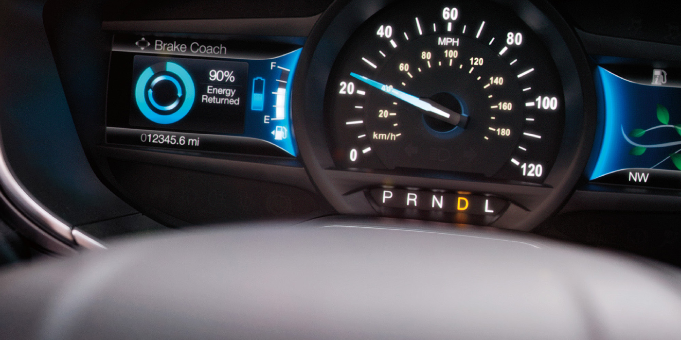
2. Turn the ignition switch to the ON/RUN position with the engine OFF.
3. Place the automatic transmission in PARK or manual transmission in NEUTRAL, as equipped.
4. Apply and hold the brake pedal. The brake pedal must remain applied throughout the park brake cable tension release process.
5. Press and hold down the electronic park brake (EPB) switch for approximately 5 seconds.
6. Observe the PARK BRAKE lamp on the instrument cluster.
7. When the PARK BRAKE lamp flashes, release then immediately press and release the EPB switch. The parking brake cable tension is fully released.
8. Release the brake pedal.
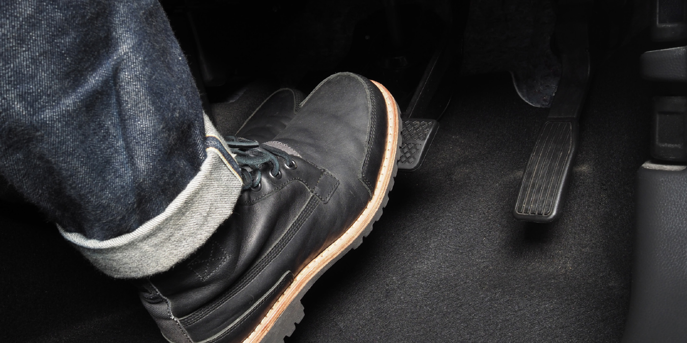
Parking Brake
Most ATSs are optioned with either a manual or electric parking brake that utilizes a drum-in-hat arrangement. To adjust the manual system, lock the pedal in the full release position and adjust the cable using the correct procedure listed in the service information. In some case, the shoes will need to be adjusted to fit the rotor.
Vehicles with the electronic parking brake have a switch in the center console, which takes the place of the manual parking brake system (the foot pedal and release handle). In case of insufficient electrical power, the electronic parking brake cannot be applied or released.
The parking brake control module has an internal motor, apply actuator, release actuator and temperature sensor. The parking brake control module also contains the logic for applying and releasing the parking brake when commanded by the park brake control switch. When the parking brake control module receives a signal from the switch, the internal circuit board temperature is checked to verify it is within operating range before the control module performs the requested operation.
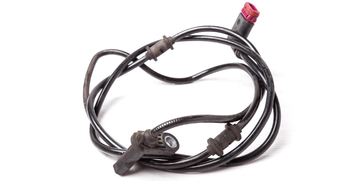
The electronic parking brake module receives hard-wired signals from the apply/release switch. The module receives wheel speed sensor signals, engine torque, gear information, and brake pedal signals through the GM-LAN. The system can be calibrated using a factory or enhanced scan tool. If you do not have a scan tool, you can use the following procedure to adjust the module:
1. Ignition ON, apply and hold the brake pedal.
Push and hold the electronic parking brake switch down for 5-6 seconds.
2. Release the electronic parking brake switch.
3. Momentarily push the electronic parking brake switch down.
4. Remove the EPB MODULE fuse and reinstall.
5. Apply the electronic parking brake.
6. Release the electronic parking brake.