added $5,000 to the showroom price of the car.
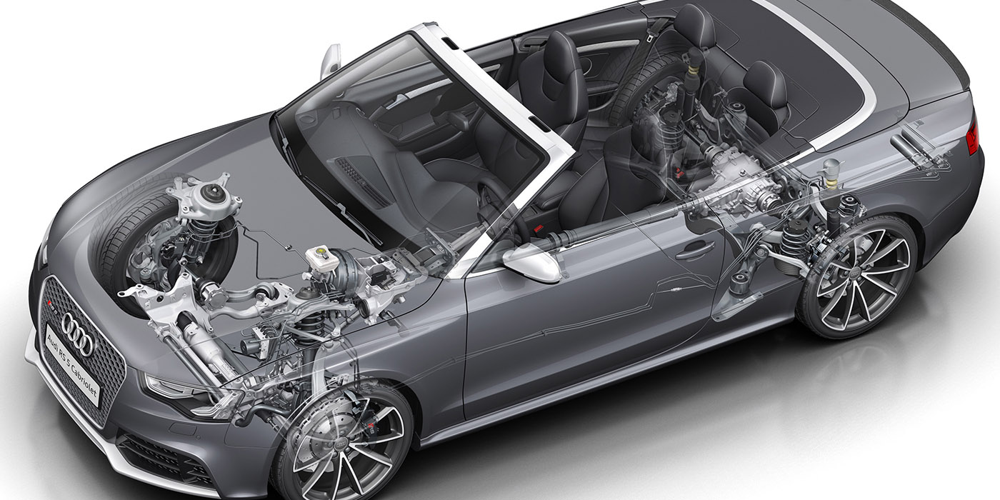
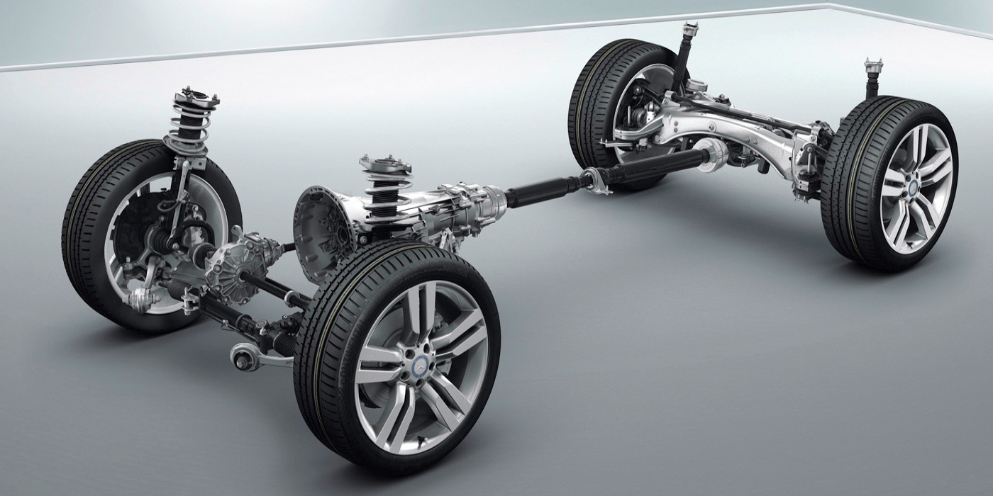
 The Mustang uses a live rear axle mounted on the vehicle with three links and a Panhard rod. None of the angles are adjustable. But, it does not mean that this is a “two wheel” alignment. The thrust angle is critical to aligning the front suspension. Also, it is an indication of the health of the bushings in the control arms.
If you have a customer that is complaining about shudder or hopping on acceleration, check the hydro bushing on the top of the axle. Also check the condition of the rear transmission mounts that can mimic the same symptoms.
Front Control Arms
Mustang makes use of an independent MacPherson-strut front suspension with reverse “L” lower control arms. On this generation of Mustang, the control and steering arms are designed to deform in case of contact with a curb or other obstruction. Compare measurements like setback and steering angle side-to-side if there are any large discrepancies.
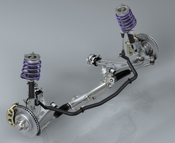
The ball joint on these Mustangs is non-serviceable and must be replaced with the entire control arm. The ball joint has a deflection limit of 0.3mm (0.012”). These loaded ball joints can be tested by pulling up and down on the control arm while the suspension is loaded. If you can feel any movement, chances are the joint is worn out.
Always tighten the lower control arm and lower ball joint nuts with the suspension at curb height.
Control Arm Bushings
The front lower control arms also use a “Hydro” or hydraulic rubber bushing in the rear mount. Also, bushings in the front control arms can change the camber and caster by ± 1.0º or more if they are worn. Visually inspect the bushing looking for any cracks or separation of the rubber from the shaft and shells.
Drivers may comment they hear a grunt, creak or chirp noise while driving over bumps, like speed bumps and curbs. This is a sign of a bad lower control arm bushing. This noise is different than a noise caused by a worn sway bar or upper strut mount. Strut mounts and sway bars will make a clicking or popping noise on these Mustangs.
There are aftermarket high performance bushings for this generation of Mustang. But, the customer may notice more noise and vibration transmitted to the vehicle if installed. For some drivers this is acceptable, but for others it could mean a comeback for your shop.
Upper Strut Mounts
Stock upper strut mounts are non-adjustable. Aftermarket adjustable strut mounts are adjustable. Some aftermarket mounts can give an addition ±2.0 of caster or camber. These parts are helpful when aligning vehicles that have been lowered up to 3”.
Camber Adjustment – Front
If camber adjustment is necessary to resolve a vehicle alignment issue, then slotting the strut at the lower mounting hole and installing a cam bolt is the recommended method. This should give ±1.75º of adjustability.
Make sure to remove the wheel speed sensor bolt and brake line bracket bolt before pulling the strut.
Do not enlarge the holes any more than indicated by the etchings on the strut mount and clean and paint the exposed metal. The bolts should be tightened to 200 Nm (148 ft/lbs.) after the adjustment is made.
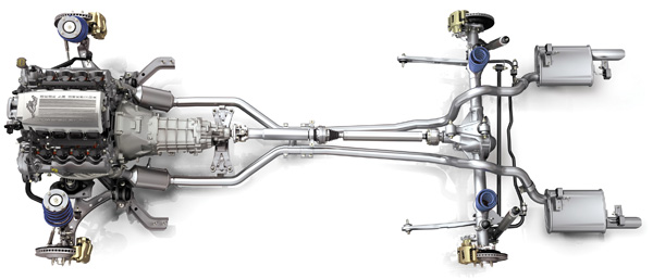
Caster Front
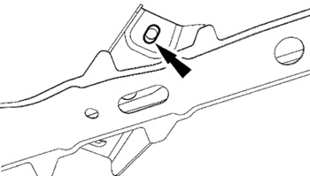
To adjust front caster, it is necessary to elongate the mounting holes in the front control arm mounting bracket on the subframe. Do not elongate the holes any more than indicated by the etchings on the subframe. This modification will yield about ±1.0 of caster. Tighten the nuts to 175 Nm (129 ft. lbs.). Adjustable upper strut mounts can be used to give ±2.00 of adjustability. But, this requires modification of the strut tower.
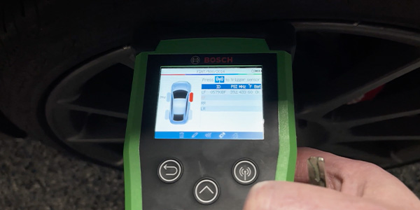
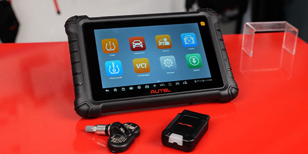
Tire Pressure Monitoring System (TPMS) Sensor Training
TPMS was standard for the 2007 model year. 2007-2009 models have banded sensors, 2010-2011 models have sensors mounted behind the valve stem.
If the vehicle has been stationary for more than 30 minutes, the sensors will go into a “sleep mode” to conserve battery power. It will be necessary to wake them up so they will transmit the latest tire pressure information to the Smart Junction Box (SJB).
Activation
1. Turn the ignition switch to the ON position.
2. Position the TPMS tool against the LF tire sidewall, 180 degrees from the tire valve stem.
3. NOTE: The TPMS tool will provide feedback in the form of a flashing green light and a beep sound for each successful response from a tire pressure sensor. Press the test button on the TPMS tool to activate the sensor, activate the sensor at least two times.
4. Repeat Steps 2 and 3 for the remaining tires.
Relearn
1. Turn the ignition switch to the OFF position. Then, press and release the brake pedal.
2. Cycle the ignition switch from the OFF position to the RUN position three times, ending in the RUN position.
3. Press and release the brake pedal.
4. Turn the ignition switch to the OFF position.
5. Turn the ignition switch from the OFF position to the RUN position three times, ending in the RUN position.
• The horn will sound once and the indicator will flash if the training mode has been entered successfully. If equipped, the message center will display TRAIN LF TIRE.
6. It may take up to six seconds to activate a tire pressure sensor. During this time, the TPMS tool must remain in place 180 degrees from the valve stem for 2007-2009 models with banded sensors and directly below the valve stem on the sidewall for 2010-2011 models with the valve stem mounted TPMS sensors.
Press and release the test button on the TPMS tool. The horn will sound briefly to indicate that the tire pressure sensor has been recognized by the vehicle.
7. Within two minutes of the horn sounding, place the TPMS tool on the correct position for the sensor and release the test button to train the right front tire pressure sensor.
8. Do not wait more than two minutes between training each sensor or the Smart Junction Box (SJB) will time out and the entire procedure must be repeated. Repeat Step 7 for the right rear and then left rear.
The procedure is completed after the last tire has been trained. When the training procedure is complete, the message center (if equipped) will display TIRE TRAINING COMPLETE.
For vehicles not equipped with a message center, successful completion of the training procedure will be verified by turning the ignition switch to the OFF position without the horn sounding. If the horn sounds twice when the switch is turned to the OFF position, the training procedure was not successful.
For information on Hunter Engineering’s Alignment & Tire equipment, click here!